|
|
|||||||||||||||||||||||||||||||||||||||||||||||||||||||||||||||||||||||||||||||||||||||||||||||||||||||||||||||||||||||||||||||||||||||||||||||||||||||||||||||||||||||||||||||||||||||||||||||||||||||||||||||||||||||||||||||||||||||||||||||||||||||
|
UPDD supports both multi-monitor and multiple pointer device configurations. This means that UPDD can cater with a system that has more than one monitor or more than one pointer device and any combination thereof can be supported by UPDD.
This document describes the multi-monitor and device considerations for each of the supported desktop operating systems.
Please ensure you read the notes section before using multi touch devices or multi touch monitors. Multi-monitor and multi-device notesSince UPDD 4.1.10 the driver utilises QT monitor matrix (QDesktopWidget class) in all OS to retrieve monitor layout information and monitor handling. For successful UPDD multi-monitor operation the QT monitor properties must see either different monitor ids or co-ordinates. Therefore the UPDD driver can only support configurations that are identifiable by the QT function and in most cases we would expect this to handle most multi-monitor configurations. Should you experience any unusual multi-monitor issues our command line utility can be used to view the system’s multi-monitor layout as seen by our driver. When using UPDD in a multi-monitor environment the following issues need to be considered: Multi-monitor configurationsThere are a number of multi-monitor configurations and it should be possible to configure UPDD to support most configurations.
Different video resolutionNative video mode allows different screen resolutions to be set on the individual monitors. Some custom video drivers may not allow different screen resolutions and all monitors will have to be the resolution of the largest resolution defined on one of the monitors. However, they may allow the viewable area to be a lesser resolution and ‘scroll’ the desktop around the full resolution. In this instance a custom segment will need to be defined to calibrate the viewable area and the scrolling capability will have to be locked as calibration does not work on scrolling desktops unless UPDD has been written to specifically interface with the video driver such that the two drivers work together and maintain calibration. This has been developed for one specialised system only. Please contact Touch-Base for more information. Multiple devicesUPDD has no restriction on the number of devices it can handle. As long as the controller can be connected via one of the supported hardware ports UPDD can be configured to support it. Hardware port binding (port and desktop segment association)In a multi-device environment a hardware port will be required for each pointer device. Most devices used in a multi-monitor/device environment are serial or USB and any of these ports can be used. In a multi-monitor / multi-touch device environment it is important to be able to associate a specific touch device (controller) with a given monitor (desktop). Serial controllers are connected to unique ports (com1, com2 etc) which offers a unique identifier to the device. For USB the binding method is different depending on the OS is use. See Binding section below for more details. Anchor mouse – Windows onlyIn a multi-monitor, touch screen environment, it may be a requirement to leave the system pointer at its current location once the touch is complete. E.g. a three monitor system where the left and right screens are touch but the middle screen is mouse driven. With normal touch drivers the cursor would be left at the last point of touch forcing the user to use the mouse to bring the cursor back to the central monitor each time a touch was made. Using the Anchor Mouse function, as found in the UPDD Console - Properties dialog, the cursor will be returned to its previous location once the touch has been processed. This is a system wide setting that effects all devices once enabled. Scrolling desktops – Windows onlySome systems support higher video resolutions than the video display can physically support. In this instance the video display becomes a ‘window’ on to the desktop and the desktop scrolls around video. In this instance touch screens cannot stay calibrated as they do not know the desktop element currently on display. For a touch screen driver to work in this environment the touch driver has to liaise with the video driver to be informed of the desktop element currently in view. This has been performed by UPDD with one video chip manufacturer and calibration was retained throughout the scrolling process. Desktop priorityDesktops can be allocated priorities when used in a multi-monitor environment and are defined in the UPDD Console - Properties dialog: The Interlock priority is a method of assigning a sharing priority to a device in a multi-device environment. Prior to introducing this function if two pointer devices were used at once the system pointer would rapidly jump between all the points of touch. This function avoids this symptom. See the UPDD on-line help for more information. The Admin priority hands control immediately to the device and is really only ever useful when one administrator desktop is in use. Setting more than one desktop introduces the issue where the system pointer will rapidly jump between all the points of touch if two or more admin desktops are touched at the same time. Given that a pen up will be forced on any Interlock device currently in use we recommend that those devices should be working with an appropriate click mode whereby the pen is not held down during use. Clone settingsMulti-monitor configurations normally require a degree of configuration in UPDD. If the configuration is to be replicated on a number of systems then UPDD has a useful facility to ‘clone’ the settings of one system on subsequent installs. Once the system is configured as required the ‘Dump settings’ function is located in the UPDD Console, Status dialog. A file is created that contains all the settings. This file is placed with the UPDD setup.exe program during the next install. See the UPDD Installation document for more information. RotateVideo rotation is catered for in UPDD and with some rotate methods UPDD can cater for rotation beyond the primary monitor. See the rotate document for more information. Multiple mouse pointers – Windows onlyIt is possible to give each pointer device in a Windows environment its own ‘mouse’ cursor, via specialised OS extensions and this is currently being investigated. WindowsEnsure the notes section at the beginning of this document is read before utilising multiple devices in a Windows environment.
The following notes refer to single user, multiple monitor configuration. If using multi-monitors in a multi-user/seat environment please refer to this document.
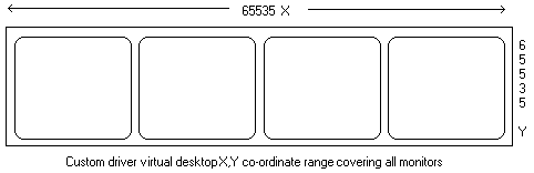
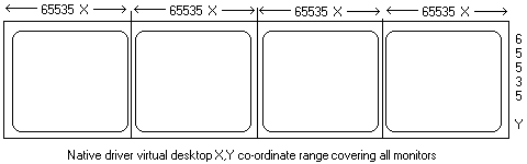
To be able to configure UPDD in these situations you need to understand how Windows caters with multiple monitors and devices, specifically how multiple monitor configurations are supported by Windows and the manner in which the desktop is defined. Desktop resolutionWe are all familiar with a single monitor displaying a complete Windows desktop, as this is the standard system configuration. We are also familiar with the concept of different video resolutions and most of us work on systems with a screen resolution of 800x600 or 1024 x768. The first figure defines the number of pixels in the X plane (left to right) and the last figure defines the number of pixels in the Y plane (top to bottom). Although these video resolutions are familiar to us Windows maps these ‘video pixel’ resolutions to its own virtual desktop resolution of 65535 (X plane) x 65535 (Y plane). Pointer device calibration data relates to the virtual desktop. When UPDD interfaces with the operating system’s virtual mouse port driver to request the system pointer to be moved to a specific X, Y co-ordinate it references the virtual desktop resolution, hence the change of user screen resolution does not affect the performance of UPDD. Depending on the type of multi-monitor support employed within the system, as discussed below, each monitor will either have its own virtual desktop of range 65535 X and 65535 Y or share one virtual desktop across all monitors, thereby each controlling a segment of the virtual desktop. The user sees the same results, that is, the desktop is spread over all the available monitors, but internally this process is handled differently.
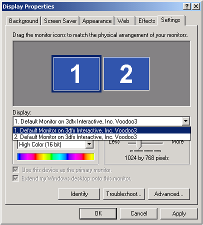
In the above examples the X and Y co-ordinates are spread across the monitors in a 4 x 1 configuration. However, with native video support each desktop has its own virtual range whereas, in the custom video support the Y co-ordinates will be in the range 0 to 65535 but the X co-ordinates will be in the range 262140. In the custom video, if the monitors were stacked in a square (2x2) then the range would be 0 to 131070 and 0 to 131070. Multi-monitor supportEach monitor is either supported by the standard Windows video drivers (Native Window support) or specialised drivers supplied with multi-video port cards (Custom and Stretched video support) as described below: Native video support Native support for multiple monitors was available with Windows 98 and has continued to be available under ME, W2K and XP. This allows for individual video cards to be placed in the system and for Windows to automatically recognise that the system has more than one video card and to show this in the desktop properties. Each monitor can then be enabled/disabled via the desktop display properties and each can have its own settings. In this environment each monitor has its own complete virtual desktop.
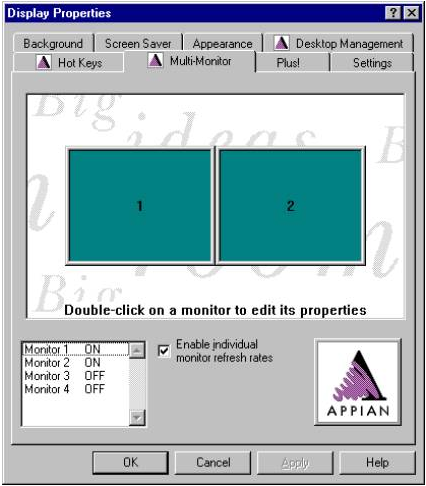
In the above example the system has two enabled monitors. Segmented video support Prior to the availability of native video support, introduced with Windows 98, video card manufactures had to develop their own drivers to implement multiple monitor support for Windows 95 and NT and, for many reasons, these drivers are still used in Windows systems that offer native support, especially where the native video drivers do not support the hardware. In this case Windows is only aware of one monitor but the custom driver handles the multiple monitor configuration. In this environment each monitor shares the virtual desktop and maps to a segment within the virtual desktop.
In the above example a Quad video card is used to offer four monitors, two of which are enabled.
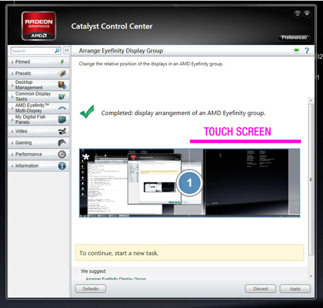
In some cases a single logical desktop (the OS sees a single monitor) can be stretched across (mapped to) individual physical monitors, as in this Windows example:
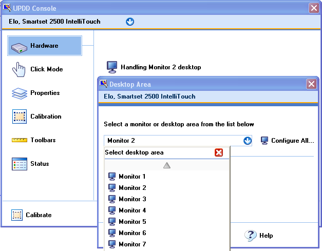
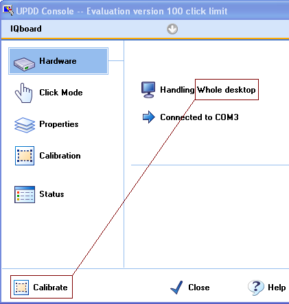
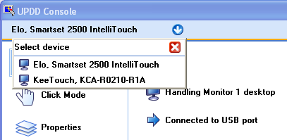
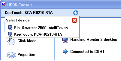
UPDD configurationUPDD is responsible for moving the system pointer on the desktop and therefore in a multiple monitor environment it needs to know the method employed to handle the video cards. Further it also needs to be aware of the monitor/desktop area to be associated with the pointer device such that the movement of the system pointer can be restricted to the associated area. UPDD uses a number of interfaces to feed touch into the OS. By default the touch screen is associated with the main / primary monitor. If the touch screen is to be associated with a different monitor, other than the Primary monitor, then the touch screen / desktop association is adjusted needs to be adjusted The UPDD Console shows the pointer devices configured in the driver. The Hardware dialog shows the monitor or desktop area associated with the current device, as shown below:
UPDD ships with a number of predefined desktop areas that take into account the different methods of video support as follows
** Segments apply by default to Monitor 1. To apply these settings to a different monitor for a given device manually set “MonitorNumberForSegment” in the TBUPDD.ini file or use the command line interface to define the setting e.g. tbutils segment “left half” setting dw monitornumberforsegment 2 sets the touch device set to left half to use the left half of monitor 2. or tbutils device 3 setting dw “monitornumberforsegment” 2 indicates that any segments defined for touch device with device handle 3 to use monitor 2. Standard desktop mode definitionIf the device is to move the system pointer across the whole desktop (being the primary monitor), as standard in a single monitor configuration, then the desktop area name is set to ‘Whole Desktop’ or Monitor 1, irrespective of video support in use. Extended desktop, native mode definitionWhen using Vista, Win 7 or Windows 8 the Extended Touch option will be available and the monitor setup is different depending on this setting.
If the device is restricted to moving the system pointer on an extended monitor, as supported by Native Video drivers, then the desktop area name is set to the name of the monitor, e.g. Monitor 2. If the dialog shows the Configure All option then this is very useful in a multi monitor system as this will automatically assign the correct desktop for all touch monitors on the system rather than having to manually assign them one at a time.
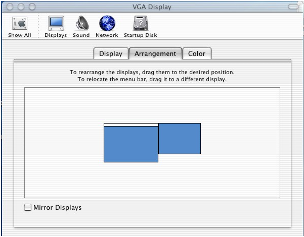
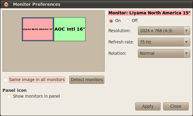
In Vista, Windows 7 and Windows 8, the UPDD extended touch feature (interface via Virtual HID) is initially associated with the Primary Monitor, e.g. in a single physical or virtual monitor setup. However, if the UPDD extended touch feature is used on an extended desktop monitor (non primary monitor) as supported by Native Video drivers, then Tablet PC settings have to be used to assign the UPDD Virtual HID device to an extended desktop monitor as described here. Once the TablePC calibration has been used to associate the VHID device with the appropriate monitor, for completeness sake you can then make the correct monitor associations in the UPDD Console. Win8 Touch Interface The Win8TI interface is initially associated with the Primary Monitor. If the device is restricted to moving the system pointer on an extended monitor, as supported by Native Video drivers, then the desktop area name is set to the name of the monitor, e.g. Monitor 2. If the dialog shows the Configure All option then this is very useful in a multi monitor system as this will automatically assign the correct desktop for all touch monitors on the system rather than having to manually assign them one at a time. Extended desktop, segment mode definitionIf the device is restricted to moving the system pointer on a specific monitor, as supported by a custom video driver, then the desktop area name is set to the name of the segment, e.g. Left half, Right half etc. Extended desktop, Stretched mode definitionIf the device is restricted to moving the system pointer on a specific monitor, as supported by a stretched driver, then the desktop area name is set to the name of the segment, e.g. Left Half – Stretched, Right Half - Stretched. Important notes: Using identical USB touch devices If a 2nd USB touch device is added and the touch device is ‘technically’ identical to the device already in use then after connection for the first time it may be necessary to reestablish relationship between touch screens and Windows desktops and recalibrate. Mac OS XEnsure the notes section at the beginning of this document is read before utilising multiple devices in a Mac OS X environment. For Mac systems that are capable of supporting more than one monitor the multi-monitor configuration is shown in the System Preferences, Hardware, Displays, Arrangement dialog as follows:
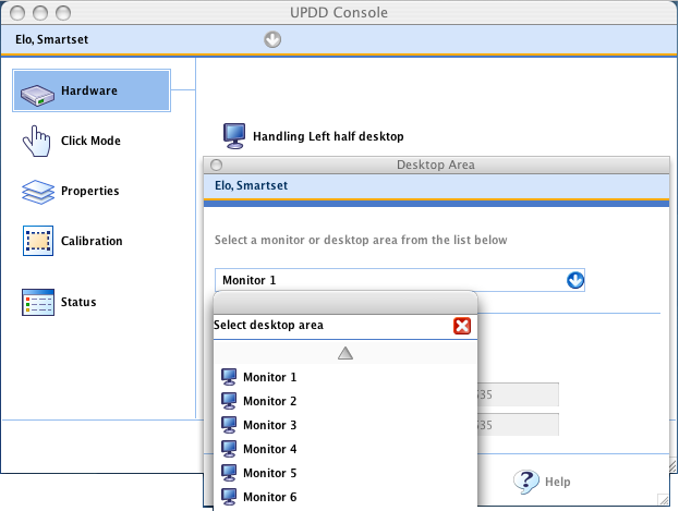
UPDD configurationUPDD is responsible for moving the system pointer on the desktop and therefore in a multiple monitor environment needs to be aware of the monitor/desktop area to be associated with the pointer device such that the movement of the system pointer can be restricted to the associated area. The UPDD Console shows the pointer devices configured in the driver. The Hardware dialog shows the monitor or desktop area associated with the current device, as shown below:
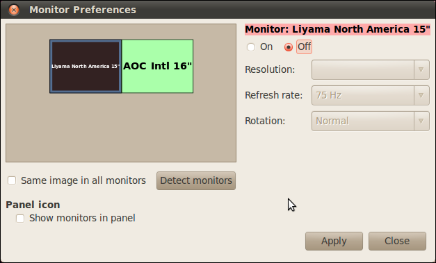
UPDD ships with a number of predefined desktop areas for use with the Mac configuration. The system has been tested with 8 touch monitors without issue. Each monitor can have a different screen resolution. In a multi-monitor environment a reboot will be require before added devices are active. External dual head devicesExternal video extenders are available for the Mac such that a single video port, typically on a Mac Mini, can be extended across two monitors. One such device. dualhead2go (http://www.matrox.com/graphics/en/gxm/products/dh2go/home.php) allows two screens to be connected to a single VGA connector on the MacMini. To the MacMini, it looks like one wide screen (2048x768). It is actually two separate flat panels each set to 1024x768. If using this device we recommend using corner calibration points (2 points, 0% margin) and ignoring the calibration points drawn in the corners of both devices and just touch the appropriate corners of the touch device. LinuxEnsure the notes section at the beginning of this document is read before utilising multiple devices in a Linux environment. The following notes refer to single user, multiple monitor configuration. If using multi-monitors in a multi-user/seat environment please refer to this document. Given that Linux supports a wide variety of monitor configurations it is important that the configuration is one that can be handled by UPDD. If the multi-monitor layout listing does not return sensible information and you have difficulty configuring UPDD to work with your configuration, it is likely that the monitor configuration needs to be tweaked so that it does. If the layout is sensible, but either the calibration screen appears in the wrong place or the mouse does not track correctly this suggests a xorg / display manager issue that probably requires tweaks in the xorg or display manager. UPDD on Linux supports the use of multiple monitors with the desktop extended (stretched) across all the monitors. With earlier releases of our software (version 4.1.1 and 4.1.8) the monitor layout had to be horizontal, left to right, such as shown in the example below for a three monitor setup: The “serverlayout” section of the xorg.conf file has the screens defined thus:- Screen 0 "Screen0" 0 0 Screen 1 "Screen1" 1920 0 Screen 2 "Screen2" RightOf "Screen1" With UPDD 4.1.10 there is no such restriction. Under Linux there are a number of ways to support multiple monitors, some generic and others specific to particular graphics cards or even Linux distribution. In this section we cover the generic method referred to as Xinerama and other methods specific to Nvidia graphics cards. As of Sept 11 we revamped multi-monitor support, to overcome multi-monitor issues reported by various customers, and fully tested for Twinview, Xinerama, and native multi monitor, with vga splits on any monitor in any of these configurations. All appears to be working as expected. XineramaFrom the web “Xinerama was originally developed by DEC (Digital Equipment Corporation) under the name of PanoramiX, and was later incorporated into the X Window System as Xinerama. Not only is Xinerama compatible with NVIDIA solutions, but also is universal to all graphics cards with supportive Linux drivers and the X Window System” and is explained in greater detail here: http://en.wikipedia.org/wiki/Xinerama. To setup a system using Xinerama you should refer to the documentation provided by your vendor or available on the web. The steps we followed to configure our Xinerama based system is outlined below as an example:
· Modified xorg.conf to add new sections for our second graphics card and monitor, and the corresponding “Screen” section to link the two together. · Added the new screen into the “ServerLayout” section using the following line:-
Section "ServerLayout" Identifier "Multihead layout" Screen 0 "Screen0" Screen 1 "Screen0 (2nd)" RightOf "Screen0" <<<<added InputDevice "Updd0" "SendCoreEvents" InputDevice "Mouse0" "CorePointer" InputDevice "Keyboard0" "CoreKeyboard" Option "Xinerama" "on" <<<<added Option "Clone" "off" <<<<added EndSection ... Machine specific sections removed … Note – This section was added on our Linux 64 because we were using an Nvidia graphics card which needed a driver to be downloaded and installed from their website. The driver had non-standard extensions that can guess the size of the screen and this stopped some X software, including our driver, from working correctly. Section "Screen" Identifier "Screen0" Device "Videocard0" Monitor "Monitor0" DefaultDepth 24 SubSection "Display" <<< This section specifies the resolutions and bitdepths of the respective monitor Viewport 0 0 Depth 24 Modes “1600x1200” “1280x1024” “1024x768” "800x600" "640x480" EndSubSection EndSection Section "Screen" Identifier "Screen0 (2nd)" Device "Videocard0 (2nd)" Monitor "Monitor0" DefaultDepth 24 SubSection "Display" Viewport 0 0 Depth 24 Modes “1600x1200” “1280x1024” “1024x768” "800x600" "640x480" EndSubSection EndSection Note the changes above enabling Xinerama and the sections specifying the screen resolutions. On some systems using the Nvidia graphics driver these are sometimes missing. UPDD does not currently support multiple monitors configured for cloned/mirrored mode (same desktop seen on all monitors) or extended desktops not using the Xinerama extensions – see http://en.wikipedia.org/wiki/Xinerama#Dual_display_X_without_Xinerama for more details. Please contact us if this is required. NouveauFrom the web “Nouveau Becomes NVIDIA's New Standard Driver Feb 22, 2010” Being the ‘new’ driver this is the default driver for Nvidia cards on more recent Linux kernels which has built in support for multiple monitors. It can also be downloaded as required. To activate multi-monitor support open System, Preferences, Monitors dialog:
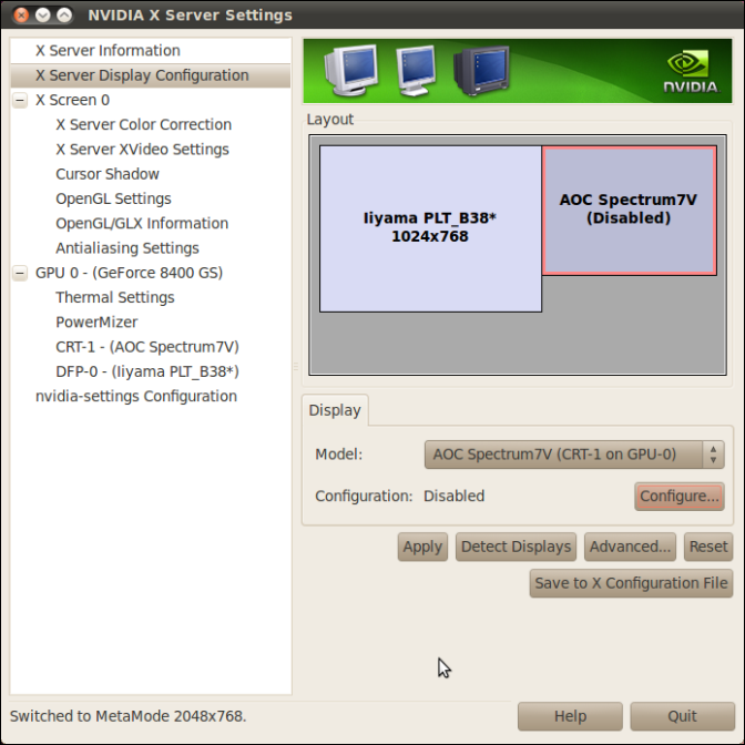
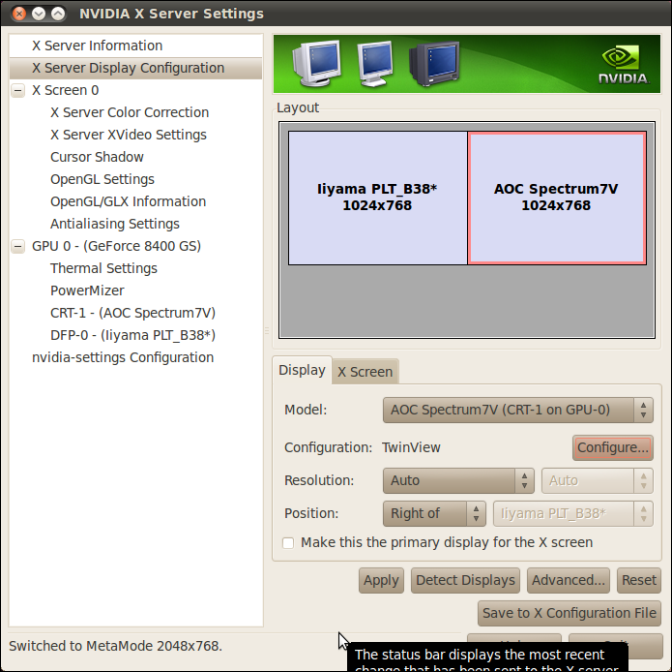
The desktop will automatically extend to the second monitor. You can now configure UPDD as usual for multi-monitor, see below. TwinviewAs taken from the web “TwinView was developed by NVIDIA for allowing multiple monitors to be powered by a single GPU with their array of GeForce graphics cards.” To implement this support use the official Nvidia driver which has support for TwinView. To activate multi-monitor support open System, Preferences, Monitors dialog:
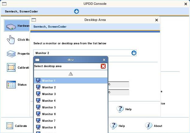
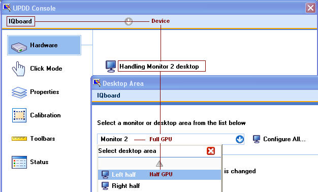
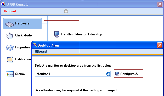
Configuring a dualhead system via twinview effectively allows one GPU to support two physical monitors. Linux will only list one monitor for each Twinview. Given this Linux view, UPDD needs to be configured to handle each half of the GPU rather than the whole monitor. You can now configure UPDD as usual for multi-monitor, see below. UPDD configurationUPDD is responsible for moving the system pointer on the desktop and therefore in a multiple monitor environment needs to be aware of the monitor/desktop area to be associated with the pointer device such that the movement of the system pointer can be restricted to the associated area. Once you have a multi-monitor system configured you should use the UPDD Console to configure your touch-screens and monitor association. This is done by going to the “Hardware” page in the Console and clicking the “Handling XXX Desktop” where “XXX” is the current desktop being handled, e.g. “Handling Whole Desktop”. You should then select the monitor or desktop segment you want to use from the desktop and monitor list.
Figure: Allocating a touch-screen to Monitor 1
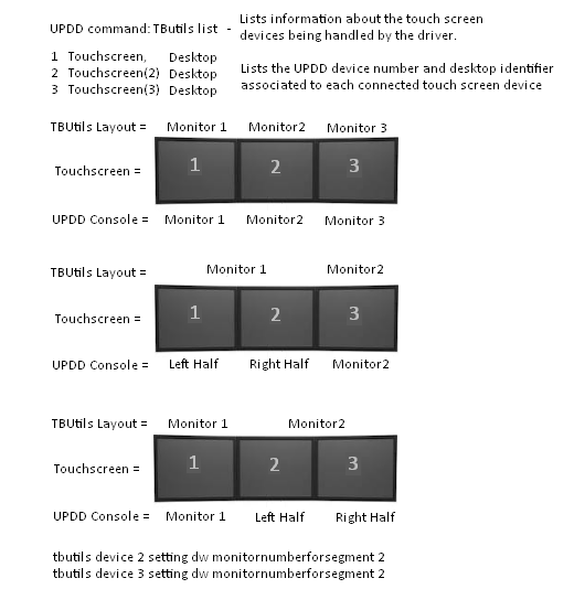
**These settings apply by default to the first defined GPU - Monitor 1. If the twinview devices are connected to a different GPU then use the setting “MonitorNumberForSegment” in the TBUPDD.ini file to specify the GPU. In this example the Twinview devices are connected to GPU seen as Monitor 2: 1) Install UPDD and plug in both touch monitors. At this point both touch devices will be assigned to ‘Whole’ desktop in the UPDD console. 2) Select the Configure All option in the UPDD Console. 3) When the screens display the cross touch the left-hand screen then cancel the calibration (esc key) 4) One of the
devices will now be set to Monitor 2. Change this to Left Half as shown: 5) Select the other device which will be defined as Whole Desktop and change to “Right half”. 6) Run '/opt/tbupddlx/tbutils list '. Note which two controllers are assigned to the left and right halves (X and Y, where X and Y are the device numbers shown in the list). 7) Run '/opt/tbupddlx/tbutils device X setting dw monitornumberforsegment 2'.(X = device number) 8) Run '/opt/tbupddlx/tbutils device Y setting dw monitornumberforsegment 2'.(Y = device number) The following example shows how three monitors might typically be configured in a Linux system:
After you have configured the monitors you will need to calibrate each touch-screen before using them. Monitor Span FeatureStarting with 5.1.1252 we have a new feature "monitor span". A touch screen can now be associated with two or more monitors.
A number of criteria must be met for this feature to work:
1) The UPDD
software bundle must obviously support the touch device but also contain a virtual device. 2) Calibration
must be conducted via the assignall feature either manually,
or automatically.
The second and subsequent times a monitor is touched via the touch screen, a
virtual device instance is created (if not already existing) and a routing
table is set up to direct touches from the appropriate segment of the touch
screen to be directed to that monitor. Or more simply put, you just need run
calibrate and the system will configure itself as appropriate. The assignall
feature much be used to set up or change this feature (manually selecting the
monitors does not create the routing table). The “configure all” option is *not*
suitable 3) To enable this
feature one or more of the device settings “monitorspanhorz” or
“monitorspanvert” must be set to a value greater than 1. Both settings
default to 1. 4) Non extended
touch only
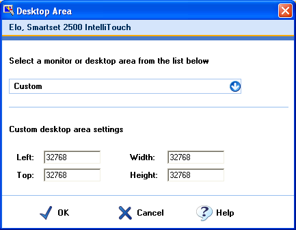
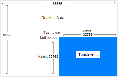
Notes: 1) The monitor resolutions are unimportant, although for practical purposes these will usually be the same. However the sectors of the touch screen must be equal in size and an associated monitor must be physically inside one of these sectors. 2) Extended touch, (multi-touch / gestures) but would require quite a complex setup so has not initially been implemented. Custom Desktop areaIn most cases it is the norm to associate a complete video display (monitor) to each pointer device. I.e. the pointer can move around the entire monitor. However, we are aware that some users may wish to restrict the movement of the cursor to a specific area on the monitor. In this case a custom desktop area can be used to restrict cursor movement to a given area on the monitor. The area is defined by specifying the top left (X min/Y min) of the area and its height (Y range) and width (X range). At the time of writing custom desktop area setting values are restricted to within the range 0 to 65535 so is only available on the primary monitor with native video support (and, under Windows, all monitors with custom video mode support). This limitation will be addressed in future releases of the driver. Native video mode supportTo define a custom desktop area, select ‘Custom’ as the desktop area and set the required logical desktop area settings, as shown in the following example:
In the above example, the touch will be restricted to the bottom right hand corner of the primary monitor, as shown below:
To apply custom settings to a different monitor other than the primary monitor you need to either: manually set “MonitorNumberForSegment” in the TBUPDD.ini file use the command line interface to define the setting e.g. ‘tbutils segment custom setting dw monitornumberforsegment 3’ indicates the device with the ‘Custom’ segment setting is to apply to Monitor 3. Custom video mode support – Windows onlyWith Windows custom video mode drivers, the entire virtual desktop, irrespective of the number of monitors, is mapped to a grid 65535 x 65535. In this mode, a custom desktop area can also be used to handle different display configurations than that catered for with the pre-defined set of desktop areas. In this mode the logical desktop settings values should be based on example values below:
E.g. In an eight monitor system, set in a 4 x 2 pattern. On all the monitors the height will be 7FFF (2 monitors deep) and the width will be 3fff (4 monitors wide). Top (Y min) on the top four will be 0 and 8000 on the bottom four monitors. Left (X min) will be 0,4000,8000,C000. Calibrating multiple devicesPrior to calibrating a device in a multi-device environment you need to associate the desktop on display on the monitor with the touch screen attached to the monitor and listed in the UPDD Console. If, for example, you had 3 USB controllers listed in the UPDD Console you would not immediately know the one to associate a given monitor/desktop and ‘trial and error’ would be needed to set the desktop with the controller until the correct match was found. To overcome this issue in a multi-monitor environment we have introduced a procedure to automatically assign a touch controller to a given desktop at the point of touch. This procedure can be invoked in 1 of 3 ways:
1) Since UPDD 4.1.8 select the standard calibrate routine where Handling Whole Desktop is defined for any device (the default after install) in a multi-monitor system. This will assign and calibrate for all listed touch devices.
2) Since UPDD 4.1.8 select the ‘Configure All…’ option in the UPDD Console, Hardware, Handling xxxxxxx desktop. This will assign only.
3) Since UPDD 4.1.6 run the calibration program with parameter /assignall. This will assign and calibrate.
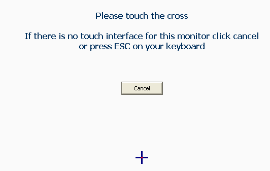
To assign the desktop/touch relationship the calibration program cycles through all discrete desktops displaying the following screen:
If touched the desktop and touch relationship is recorded in the settings. If not touched this screen is displayed on the next monitor. If calibration is also to be performed the calibration screen is also displayed on each touched screen.
1) These calibration options (assign all / configure all) are only useful where each touch screen is to be associated with a discrete desktop monitor. Where an individual logical desktop is stretched or mirrored across multiple physical monitors then manual configuration will still be required.
2) To configure desktop / touch screen relationships without performing calibration use the /configureall option.
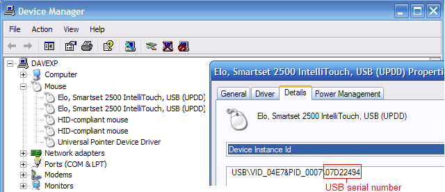
3) This procedure is especially important when using multiple graphics cards where in some instances the Monitor number seen in the Windows Display Properties does not correlate to the internal display reference used by UPDD**. E.g. we have a 3 monitor system with 3 x dual graphics cards where the display properties shows one of the monitors as Monitor 3 but the actual internal display name relates to Monitor 5! In this case Monitor 5 needs to be selected and this would not be known by an end user. This option will set the desktop segment to that needed to correctly address the monitor during calibration and system pointer placement. ** due to some issues we observed under Windows 7 we changed the way we reference the internal video address space and this change has resulted in internal video reference names not always being the same as the name shown by the desktop properties. The names show by the desktop properties relate to the physical number of monitors connected whereas the internal names relate to the video adaptor in use, in most cases they are one of the same, but not always. Controller and desktop bindingIn a multi-touch device / monitor system a mechanism is required to associate the touch device with its UPDD setting (desktop area, calibration data etc) such that the association between the settings and the device is retained across reboots or if touch controllers are unplugged and replugged. In the case of serial ports UPDD settings are bound with a touch device on a given serial port and therefore is bound to the port. If the device is plugged to a different com port then normally manual intervention is required to change the settings to refer to the new com port (unless the serial device is auto-detected in which case it utilizes controller binding) With USB devices, plugged randomly in to any USB port, binding is straight-forward in single device systems as only one device needs to be bound with the current UPDD settings. However, in multiple touch device environments, the binding is more complex, especially where the USB controllers are identical in characteristics. Depending on the USB devices in use in a multiple touch device environment the driver will either perform direct controller binding or USB port binding, as discussed below: WindowsWith a USB device, UPDD creates an internal bind key that is held as part of the UPDD settings for that device such that the key can be used to associate the device with its settings such that, for example Depending on the characteristics of the USB controller the controller will either be seen by UPDD as unique or identical UniqueFor USB devices utilizing a unique serial number or iproduct per usb controller the bind key is held in the format: P:n:vid:pid:iproduct:serialnumber – See Bind key components for more details e.g. controllerbindkey=U:0:1255:7:2:07D22494 This effectively means the UPDD settings are associated directly with the controller. Irrespective of the number of touch controllers in use or the unplugging or replugging sequence, controllers with unique characteristics will always be correctly associated with their settings as the binding directly relates to the controller connected. Note: When UPDD examines the full bind key, if the controller has iproduct binding enabled in our controller definition, the serial number is ignored (allowing the iproduct to be used instead). IdenticalFor USB devices without serial numbers and using the same iproduct per usb controller the bind key is derived in one of two ways: Version 5.1.x build 1058 and later – Win 7 and above By default, under updd 5.1.x, with Win 7 / 8 the bind key is derived from the physical location of the device on the USB hub, referred to as the DevicePropertyLocationInformation. E.g. Port_#0004.Hub_#0003 Note – due to a bug in XP API the returned information is incorrect resulting in an incorrect bind key with this method .e.g.: controllerbindkey=U:0:1032:12288:2:Optical Touch Screen Version 5.0.2 and before and 5.1.x and XP By default, under updd 5.0.2 and Windows XP, the bind key is derived from the device instance referred to as the DeviceInstanceId. This is a key generated by Windows to identify a connected USB device. A typical DeviceInstanceId looks like this. USB\VID_14C8&PID_0005\6&F6C51B9&0&4 Although Windows documentation does not detail how this value is derived, in practice we find this usually provides a reliable association. However in cases where settings are moved from one system to another this value can change. This results in a UPDD bind key as follows P:n:vid:pid:iproduct:deviceinstance – See Bind key components for more details e.g. controllerbindkey=U:0:1072:1288:2:{4d36e96f-e325-11ce-bfc1-08002be10318}\0005 This effectively means the UPDD settings are associated indirectly with the controller connected via the port Switching the default behaviour to the alternative method is controlled by a UPDD settings tbupdd.ini setting file. updd\parameters -> usbbindmode=0x01 The default behaviour can be enabled with updd\parameters -> usbbindmode=0x00 An easy way to do this is using tbutils with the command tbutils nodevice setting dw usbbindmode 1 This sets the alternate behaviour for the updd version in use. Changing this after devices are setup will lead to unpredictable results.
Binding considerations Where a single touch controller is used and irrespective of the unplugging or replugging sequence a single identical controller will always be correctly associated with its UPDD settings as being the only controller connected effectively makes it ‘unique’. For multiple touch controllers that are identical and of the same type it is important that bind keys are created for each port. This caters for the situation where the devices are randomly passed to the UPDD driver by the OS, such as at a reboot or where two devices are connected at the same time. If UPDD just associated the device in the order in which the device was passed from the OS to the driver the sequence of devices would change, as would calibration, such that touching a device would move the cursor on another device. Once plugged in and with the UPDD setting established the binding will be correct over a reboot, However, when new identical controllers are added (See 1 below) or multiple instances of same identical USB controllers are unplugged and replugged into different usb ports (see 2 below) may result in incorrect associations between the device and UPDD settings or a new device appearing in the UPDD device list Multiple USB device issues with identical devices:
Given the above issues we strongly recommend that in multi-device environments, when using identical controllers, to avoid randomly disconnecting and reconnecting devices in to different USB ports. Bind key logicFor those interested, the bind key logic is as follows. When a USB controller is discovered the system creates the bind key and this is used to determine if settings already exist or if a new device has been plugged in. Since UPDD 4.1.6, build 1150, the binding look up code first uses a partial part of the key (P:n:vid:pid) when scanning the current UPDD settings looking for the same partial key associated with a single, inactive (unplugged) device. If found then these settings are used. If it is not found, or not found with an inactive device, or there are more than one of the same identical device, then the full key used in the scanning and if found these settings are used. If neither key is found a new device is created in the UPDD device list. Bind key componentsThe bind key components are described below:
Example multi-device configurations· Multiple monitors with the desktop spread over the monitors This configuration allows the desktop to be expanded over many monitors to offer more real estate on which to run the applications. All or some of the monitors may have a touch screen fitted. Each touch monitor will be configured to control its specific desktop area. The following example shows two touch screens, one USB and one Serial, configured on separate monitors supported by the native OS video drivers.
|
|||||||||||||||||||||||||||||||||||||||||||||||||||||||||||||||||||||||||||||||||||||||||||||||||||||||||||||||||||||||||||||||||||||||||||||||||||||||||||||||||||||||||||||||||||||||||||||||||||||||||||||||||||||||||||||||||||||||||||||||||||||||


· Multiple monitors with the same desktop shown on all the monitors
This configuration, often referred to as Mirrored Displays, allows the same desktop to be shown on more than one monitor. All or some of the monitors may have a touch screen fitted. Mirrored displays can either be a system setting when more than one video controller is used or can be achieved with an external video splitter, which strictly speaking is not a multi-monitor configuration as the system will normally have only one video card. Each touch monitor will be configured to control the ‘whole’ desktop.
· Single touch screen monitor with additional pointer devices
This example illustrates UPPD supporting a touch screen monitor and an additional pointer device, such as an electronic white board or digitizer. In this example both devices will be set to control the ‘whole’ desktop.
Contact
For further information or technical assistance please email the technical support team at technical@touch-base.com