|
The
need for calibration is unique to absolute pointer devices, such as a touch
screen or white board. Unlike mouse or keyboard applications where the cursor
is part of the image, a touch screen is a physical overlay or layer with an
independent coordinate system. Only by knowing the position of the image can
the touch screen coordinates be converted into image coordinates, hence the
need to align the two different co-ordinate systems.
Besides
the differences in touch screens and controllers, calibration also
compensates for the variation in video image among displays. The image is
affected by horizontal and vertical adjustments on the monitor and by the
physical mounting of the touchscreen.
Additional
calibration complications include image blooming, where bright-colored images
expand, and the "pin cushion" effect, which causes the corners of
the display to be stretched. Poor display linearity can cause similarly-sized
boxes to be larger at the edges of the screen than they are in the middle, or
vice-versa. The displayed image can also be tilted. Even changing video modes
can affect the screen size. If images are projected onto a white board from
the side, top or bottom of the board then the image will not always be
perfectly rectangular, this is known as keystone image.
Perfect
calibration cannot be achieved in all circumstances. For example, the user
can encounter parallax problems with a change in position, or because the
present user is not the same stature as the person who calibrated the screen.
Even the most sophisticated calibration techniques can only partially
overcome such variations. To cater for the controller and video variations
UPDD uses a number of calibration techniques to ensure best results for any
given combination and this document covers all aspects of UPDD calibration
issues.
As discussed,
calibration is required to align the pointer device co-ordinate system with
the video co-ordinate system. When using an absolute pointer device the mouse
cursor should normally position itself under the stylus when it is in contact
with the pointer device. If this is not the case then calibration will be
required. The UPDD driver also supports Toolbars, which also require
calibrating, and this is covered in full in a separate Toolbar
document. This document covers the new calibration feature in UPDD
Version 4.
Under
UPDD the calibration program used to perform manual calibration is called
TBcalib. Other ways of achieving calibration are discussed in the notes section of this document.
Given
that TBcalib is a common component across all platforms and is utilised in
all environments we have also exposed in this program common UPDD User Interface calls as a simple
method for changing some of the UPDD settings that would normally be changed
from applications using the UPDD API interface.
Defining
Calibration
For
Windows, Mac OS X and Linux, manual calibration settings can be configured in
the UPDD Console, Calibration dialog:
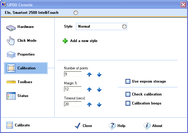
This
dialog defines the number of calibration points, the calibration timeout and
the margin percentage. These settings are defined for each defined device and
calibration style.
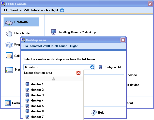
UPDD Devices
Each UPDD
configured pointer device will be listed in the UPDD Console. Each device is
given a ‘name’ and the current device is listed in the console program. Each
device is associated with a Desktop segment which indicates the area of the
desktop handled by the pointer device.
In this
example the devices has been named ‘Elo, Smartset 2500 IntelliTouch - Right ‘
to indicate to the user it is associated with the right hand monitor in a
multi-monitor configuration and has been associated with desktop segment
‘Monitor 2’.
Each
device is also allocated a unique internal device handle which is held in the
UPDD configuration file and available via the UPDD API to applications that
interface directly with the devices.
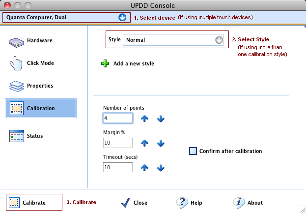
Invoking Calibration
Manual
calibration can be invoked in various ways:
·
Calibrate
option in the UPDD Console
This
will calibrate the currently selected device and calibration style.
Note:
When calibrating for the first time in a multi-monitor environment all
devices will be calibrated in such a way as to also set up desktop
/ touch device relationships. Note – this is triggered if any of the
devices are set to ‘Whole’ desktop segment.
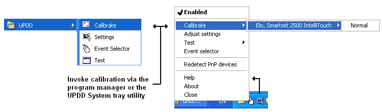
·
Directly
calling the calibration program manually
Windows options
Desktop short cut
May exist under Mac OS X and Linux on the
desktop after install. On Mac OS X a shortcut is also placed in the utilities
folder. Depending on the Linux Desktop Manager in use this is not always
setup automatically by the install procedure. Should be seen if using KDE.
These
methods of invoking the UPDD Calibrate program (which does not pass any
control parameters) invokes calibration for the current device and its
calibration styles and toolbars (unless they are defined relative to the main
video calibration). Control parameters that can be passed to the UPDD
calibration program to perform other calibration options are discussed below:
Manually calling TBcalib program (only method
available in OS where UPDD Console not available)
The
calibration program is located in the UPDD application folder and can be
invoked manually as shown:
|
OS
|
Command
line via a terminal window or shortcut
|
|
Windows
|
C:\Program
Files\UPDD\tbcalib.exe
|
|
Linux
|
/opt/tbupddlx/upddcalib
(Linux script to invoke the tbcalib application)
|
|
Mac
OS X
|
UPDD
version 4: /tbupddmx/tbcalib.app/Contents/MacOS/tbcalib
UPDD
version 5: /Applications/Utilities/UPDD\
Calibration.app/Contents/MacOS/tbcalib
|
Passing
TBcalib parameters if/as required.
·
Program control via the UPDD
calibration API calls
In
the unlikely event that TBcalib cannot be called from a program to perform
calibration, calibration procedures can be embedded in user written
applications using UPDD API calls. Refer to the Calibration
API document or email the technical support team at technical@touch-base.com for
additional information.
Calibration Procedure
Once
invoked the calibration screen is displayed requesting that each calibration
point be selected in turn.
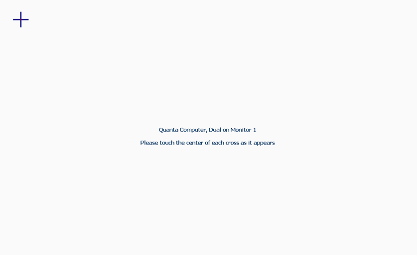
The
number of points shown and the position of the points are defined by the
calibration settings in the UPDD Console, Calibration dialog. If the margin%
setting is less than 5% arrows will be shown for points along the edges of
the screen rather than crosses. Various sizes of crosses are employed
depending on the pixel width of the calibration area. The larger the width
the greater the size of cross is used. If calibration is aborted or times out
the driver discards the updated calibration data and reverts back to the
previous data.
The
calibration data is calculated for each calibration point based on an
averaged sample of touch data packet received when touching the calibration
point.
When the
calibration margin is 5% or more for each calibration point the visual feed
back of the calibration sequence is shown below. When the calibration margin
is < 5% arrows are used for the calibration targets and only the final
green check is shown.
|
Initial cross
|
|

|
When
the calibration margin is 5% or more for each calibration point a target
(cross) is shown.
|
|
Initial touch
|
|

|
As soon
as any data is received a light coloured circle is shown around this
target.
|
|
Good data sample
|
|

|
When
the calibration point is ready to be accepted (enough time has passed while
touching) a dark circle is shown around the target.
Note:
If the touch is not sufficiently long in duration the original cross icon
is re-shown.
|
|
Ack stylus lift
|
|

|
After
the successful recording of a point a green checkmark is shown at the
successful point and any next calibration point is shown
|
|
A
number of settings are available to fine tune this behaviour for specific
controllers.
The
default values are selected to work for most controllers.
A value
of zero for any setting will select the default.
These
settings are described below and can be adjusted using the UPDD command line utility:
|
|
calibsample:minms
device
specific
default
500
units
milliseconds
|
The
minimum time the user must touch the screen for the calibration point to be
accepted.
The
granularity of this timer is 100ms
When
the calibration margin is less than 5 percent (and therefore visual
feedback is not active) the default value is 100 ms
|
|
calibsample:usesamplestart
device
specific
default
3
units
data packets
|
When a
touch is complete the data selected for the calibration option starts at
this number of packets from the end of the received stream, or the first
packet if the stream is too short. E.g. if 100 packets are received during
the touch then the sampling starts at packet 97. The calibration value is
the average of the values in each sampled packet.
|
|
calibsample:usesampleend
device
specific
default
3
units
data packets
|
When a
touch is complete the data selected for the calibration option ends at this
number of packets from the end of the received stream, or the first packet
if the stream is too short. E.g. if 100 packets are received during the
touch then the sampling ends at packet 97. The calibration value is the
average of the values in each sampled packet. This value must be >= calibsample:usesamplestart
|
Important
notes:
- UPDD
disables pointer movement during calibration so there should be no
cursor movement. However, if the pointer is moving but the calibration
touches are ignored it is likely that a different driver is in control
of the device, not UPDD.
- If the
calibration screen is not drawn full screen or is distorted or offset in
anyway then it is likely that the graphics system does not supported the
method employed to force full screen drawing. In this case a different
approach is needed as described in the Calibration Notes, Calibration
Style entry below.
- If
using EEPROM calibration on devices where the calibration pattern is
dictated by the firmware in the controller, the firmware may return a
failed status to the calibration program if the touches on the
calibration crosses are calculated to have not been in the correct
relative position. E.g the 3M SCxxx 3 point EEprom calibration is based
on a triangle and trigonometry is used by the firmware to calculate
quite accurately where the 2nd and 3rd touches
should be occurring. Recalibrate if a failed status is seen until
calibration is accepted.
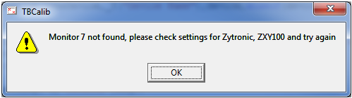
- Under
Windows, if the defined monitor is not found on the system the following
message is displayed:
Calibration Notes
Calibration
is a fundamentally important feature for pointer devices as successful usage
is reliant on correct desktop alignment. UPDD implements some important
features to ensure the calibration procedure produces the best possible
results.
Where the
following notes refer to calibration settings as held in the system the
following applies;
|
UPDD
version
|
Operating
system
|
Location
|
|
UPDD
3.x.x and 4.0.x
|
Windows
|
registry
at HKEY_LOCAL_MACHINE\SYSTEM\CurrentControlSet\Services\TBUPDD
|
|
UPDD
3.x.x and 4.0.x
|
Linux
and Mac OS X
|
tbupdd.reg
|
|
UPDD
4.1.x
|
All
OS
|
tbupdd.ini
|
The
following issues should be considered when setting up UPDD’s calibration
features:
·
Calibration
methods
Installing UPDD
for the first time will require that the device is in some way calibrated and
a number of options exist as discussed below:
Manual Calibration. The user executes the calibration program and
touches a series of displayed points on the screen. For embedded environments
data recorded in this way may be lost when the device is reset (if the UPDD
settings are is not held in persistent memory) unless the data is stored in
the touch controller’s EEPROM. An OEM using manual calibration, where the
calibration data is lost over a reboot, needs to decide on a strategy for
initiating the manual calibration. E.g. executing the calibration program at
start-up, or placing an icon on the desktop.
1st Touch calibration. Builds of the software can be supplied
with a setting such that the first touch on the touch
device after install will invoke manual calibration – this is currently a
Windows only option.
Auto-calibration. If a calibration has not been performed the driver will
try and scale the received co-ordinate with the desktop area. The calibration
calculation is based on the maximum theoretical range of values (from the
number of bits in the touch data packet) assuming that the available touch
area is exactly the same size as the visible desktop area. This relies on
the correct range of data bits being defined in the UPDD controller
definition and that the orientation of the touch screen matches the UPDD
invert X, Y settings and Swap XY settings.
Pre-calibration. Builds of the software can be supplied with pre-defined
calibration data. The calibration data is determined for a device – or class
of device - and stored in the initial UPDD settings file and installed as
part of the install procedure. See dump4tba calibration
option below for further details.
Hardware – Some controllers, once calibrated using a controller
specific hardware calibration, will output scaled co-ordinates. UPDD invokes
this type of calibration for some controllers – see EEprom
document for more information.
EEprom – Calibration is stored in controller eeprom and retrieved by
running TBcalib eeprom at system startup. UPDD stores calibration data for
some controllers - see EEprom document for more
information.
·
Calibration
Style
Each UPDD device
can have any number of calibration styles. In most cases a device will have
a single style. However, some pointer devices can legitimately have more than
one style, with each mode being calibrated separately. For example, a
whiteboard can be used for drawing to the extreme corners and would be
calibrated to the corners to ensure the whiteboard was fully calibrated.
However, a desktop could be projected onto the whiteboard such that it did
not fully cover the entire whiteboard area and therefore would need a
different calibration to be accurate when used in projected mode. In this
scenario, two calibration styles could be defined, say Whiteboard and
Projected, and calibrated separately, thus avoiding recalibration every time
usage of the board is switched. Switching stylus can be handled manually,
command line interface, toolbar or via the UPDD API.
Reserved style names
A number of style names have been used to cater for certain unique
calibration features as described below:
|
Style
name
|
Purpose
|
|
Custom2Point
Custom4Point
|
This
style has been reserved for situations whereby a system cannot handle the
methods used by the calibration program to force full screen with
unpredictable results. In this situation define a style called Custom2Point whereby calibration
does not attempt full screen mode (and therefore cannot draw accurate
calibration points) but instead requests that the top left and bottom right
corners of the calibration area be used as the calibration reference
points. No other calibration patterns are catered for.
|
|
RXXXXxYYYY
(e.g.
R1024x768)
|
On most monitors the desktop display is shown in exactly the
same place irrespective of video resolution and therefore in most cases a
single calibration is all that is required to cater for calibration in all
video resolutions. However, in some circumstances, an unusual video mode
may result in the display shifting to a new position and therefore, on a
touch monitor, the calibration will be inaccurate whilst in this
resolution.
This style name is used to associate a calibration to a
specific video resolution. The name of the style indicates the
associated resolution, i.e. R1024x768 and will be automatically selected
when the resolution is active.
Once the driver has automatically selected a resolution
specific style it will only ever switch to a new style in a different
resolution if an associated style is found.
Notes: Dropped from version 4.1.10 as with modern monitors and
video cards the image was normally in the same location, irrespective of
resolution, so we thought this function to be redundant. However, this
function has been re-instated in 5.0.2 (Oct 13) with the following
considerations:
To enable this function within the driver setting upddvideores
should be defined in the tbupdd.ini file and set to 1. This can be
performed with command “tbutils nodevice setting dw upddvideores 1”
This only works in Windows on single monitor systems.
|
|
Rotate0,90,180,270
|
On most monitors the desktop display is shown in exactly the
same place irrespective of the degree of rotation and therefore automatic
adjustment (90°,180°,270°) of the calibration data taken from a single
calibration is all that is required to cater for all rotated video
resolutions. However, in some circumstances a rotate may result in the
display shifting to a new position and therefore, on a touch monitor, the
calibration will be inaccurate whilst rotated.
These style names are associated to a specific degree of
rotation and will be automatically selected when the rotation is active.
Names are case sensitive.
If defining a style for 90,180 or 270 then a Rotate0 style
must also be defined to allow the driver to switch back to a style
associated with standard Landscape (0° mode).
|
·
Cursor
movement
No cursor
movement will take place if a stylus selects any area outside the main
calibrated area or within a calibrated toolbar. This is now configurable.
By default, no cursor movement takes place except in the main calibrated area
but this can be configured otherwise if required.
·
Calibration
data storage
Calibration settings
and the actual calibration data is held within the system or on the touch
controller’s EEPROM (where available and
supported). When stored in the system, and depending on the OS and the UPDD
version in use, it is either held in the registry under Windows or a UPDD
settings file.
EEPROM
Some
controllers can store the data on the onboard EEPROM and if this is available
a EEPROM check box will be shown on the calibration dialog. Your specific
usage of the calibration data will determine what setting to select. Using
EEPROM calibration may restrict the calibration points to specific locations
as dictated by the controller’s EEPROM calibration procedure.
If
EEPROM is used:
UPDD
3.x or 4.0 the UPDD registry entry or registry file setting
HKEY_LOCAL_MACHINE\SYSTEM\CurrentControlSet\Services\TBUPDD\Parameters\{guid}\{Device
Number}\EEPROM Calibration will be set to 1.
or
UPDD
4.1.x the [UPDD\parameters\{Device Number}\EEprom Calibration] entry in the
UPDD settings will be set to 1.
EEPROM
usage and considerations are explained in full in the separate EEPROM document
System
If
EEPROM is not supported or not enabled then the calibration data it is either
held:
UPDD
3.x or 4.0 the UPDD registry entry or registry file setting
HKEY_LOCAL_MACHINE\SYSTEM\CurrentControlSet\Services\TBUPDD
\Parameters\{guid}\{device number}
UPDD
4.1.x [updd\parameters\{device number}]
The
specific values used are: -
Number
Of Calibration Points
RefX0,
RefX1, RefY0, RefY1 *
CalX0,
CalX1, CalY0, CalY1*
InvertX,
InvertY, SwapXY
*If
“Number Of Calibration Points” is greater than 2 then there will be
correspondingly more of these values.
·
Absolute
pointer devices
Calibration is
only required for absolute pointer devices. Relative pointer devices such as
mice and touch pads do not require calibration.
·
Calibration
Bounce
A calibration point is processed when stylus contact is removed (pen up) and
the next calibration point is displayed. If a stylus ‘bounces’ on a
calibration point, thus producing two pen up’s, then the next calibration
point will be satisfied by the erroneous second pen up requiring the
calibration process to be restarted – which can be annoying if calibrating
with many calibration points. This is known as ‘Calibration bounce’. To avoid
this problem UPDD implements a setting called ‘Min Cal Delta’. This value
indicates the number of co-ordinates that must differ between the calibration
points for the next point to be accepted. If this value is set to zero this
feature is effectively disabled.
UPDD 3.x or 4.0 the UPDD registry entry or registry file setting
HKEY_LOCAL_MACHINE\SYSTEM\CurrentControlSet\Services\TBUPDD\Parameters\{guid}\{Device
Number}\Min Cal Delta.
UPDD 4.1.x [updd\parameters\{device number}\ Min Cal Delta]
·
Check
Calibration
At the end of the calibration process the new calibration data is stored and
used immediately. If the calibration procedure produces poor calibration,
possibly due to calibration bounce or inaccurate calibration point selection,
then recalibration will be needed. However, if the calibrated device is the
only pointer device in use then it may not be possible to invoke the
calibration procedure due to poor calibration! A catch 22 situation! To avoid
this problem a ‘Check Calibration’ option can be enabled in the calibration
dialog, such that the ‘Confirm’ button shown at the end of calibration must
be selected for the new calibration to be used. Failure to select the confirm
button within a certain time will result in the new calibration data being
discarded.
UPDD 3.x or 4.0 the UPDD registry entry or registry file setting
HKEY_LOCAL_MACHINE\SYSTEM\CurrentControlSet\Services\TBUPDD\Parameters\{guid}\Check
Calibration
UPDD 4.1.x [updd\parameters\Check Calibration]
·
Calibration
Timeouts
The Calibration
procedure will automatically terminate if the calibration point or confirm
button (if enabled) is not selected within the timeout threshold setting.
UPDD 3.x or 4.0 the UPDD registry entry or registry file setting
HKEY_LOCAL_MACHINE\SYSTEM\CurrentControlSet\Services\TBUPDD\Parameters\{guid}\Calibration
timeout
UPDD 4.1.x [updd\parameters\Calibration timeout]
Since 4.1.6 a setting of zero disables timeout.
·
Calibration
Beeps
The Calibration
Beeps option (if available) will generate a sound when the calibration point
has been selected. Useful if calibration is being done remotely from the
system or desktop.
UPDD 3.x or 4.0 the UPDD registry entry or registry file setting
HKEY_LOCAL_MACHINE\SYSTEM\CurrentControlSet\Services\TBUPDD\Parameters\{guid}\Calibration
Beeps.
UPDD 4.1.x [updd\parameters\Calibration Beeps]
Under Linux the calibration beeps require a soundcard as we have not been
able to access the internal pc speaker in Linux. The playback is performed
using a sound utility called “sox” which seems to be installed by most
mainstream Linux distributions. We play a sound file called beep.wav to
emulate the sound is of a “click”.
·
Pointer
Device Orientation
UPDD expects
pointer devices to be orientated such that the 0,0 (origin) co-ordinate is
being generated from a known point on the device. If the device is
incorrectly fitted, say in the case of a touch screen attached to a monitor,
and it has been fitted ‘upside-down’ then the cursor will move in the
opposite direction to that expected. If the number of calibration points is 4
or more then the calibration procedure will automatically calculate the
orientation. Using 2 or 3 point patterns will require that the pointer device
is fitted correctly with the origin co-ordinate being generated from the
expected position. It is for this reason that we recommend a 4 point or
more calibration pattern is used.
·
Calibration
Algorithms
UPDD
employs four calibration algorithms;
- A standard algorithm that works well
for devices with good linear characteristics. This algorithm is used
with all calibration patterns except 4, 9 and 25 points.
- An advanced algorithm that works
best on devices with poor linear characteristics. The advanced algorithm
is used when the device is calibrated with 4 (except 20% in – see below)
or 9 point calibration patterns. This algorithm is more dependant on the
accuracy with which the calibration is done so it is very important to
calibrate with a stylus that can select the exact centre of the
calibration cross or tip of the calibration arrow (in 0% in
calibration).
- 4 point XY coefficient algorithm. This
algorithm, introduced with UPDD version 3.8.24, is used when the touch
media has linear distortion, such as shearing or keystoning. Typically
used when projecting images onto electronic whiteboards from the side,
top or bottom. This algorithm is invoked when the calibration pattern 4
point with 20% margin is specified.
- 25 point distortion algorithm. This algorithm
caters for severe non-linear distortion.
Importand
note: UPDD supports calibration segments which are intended to support cases
where a touch interface does not cover the whole of the operating system
desktop or the whole of a physical monitor. For example where a video
splitter splits the OS desktop to 2 touch monitors, or where a touch screen
smaller than the physical monitor is used, perhaps as a soft keypad in part
of a larger display. When used as described above there are no known issues
with this feature.
However
we are aware that some users test this feature on systems that are not
configured as described as above. In some cases unusual results can be seen,
in particular when certain calibration patterns are used. With 2,4,9 & 25
point patterns no problem should be seen. For other patterns the calibration
algorithm is based on screen zones and the nearest zone to a touched point is
used. When a point > 100% outside the calibrated area is touched this
algorithm is ineffective and the touch result is incorrect.
This
only occurs on a system not configured as intended for this feature. In the
unlikely event that a user has a real need to use such a configuration then
the problem can be avoided by selecting 2,4,9 or 25 point calibration.
Another possibility depending on the required usage is to use the UPDD
toolbar feature to mask off unused areas of the screen.
The
algorithm used for 4,9, 25 point calibration is in fact the most accurate in
most cases, so this should not present a problem.
·
Rotational
Software
Software can be
used to rotate desktops through 0, 90, 180 and 270 degrees. UPDD can
automatically cater for rotated desktops and readjust calibration. See the rotate documentation.
·
Multiple
monitor and devices
UPDD can support
any number of pointer devices and desktop segments. A desktop segment is the
area of the desktop associated with the device. E.g. In a two monitor system,
both with touch screens fitted, the entire desktop could be spread over the
two monitors. In this case each touch screen is associated with one monitor
being half the desktop. The calibration procedure will take place on the
individual desktop segment associated with the device and cursor movement
will be restricted to that desktop segment when the device is in use. See
the multi-monitor
and device documentation for further details.
·
Video
Resolution
Windows:
.Windows calibration is based on a ‘virtual’ desktop resolution that
represents the physical desktop resolution and calibration data is relative
to the virtual resolution. In most cases a single calibration is all that is
required to cater for calibration in all video resolutions as changing screen
resolution does not normally require a recalibration as the video display is
normally in the exact same position and therefore the ‘virtual’ and ‘real’
resolution relationship produces accurate calibration. However, on some
systems a new calibration may need to be performed in the new resolution if
the resolution switch results in a repositioning of the video display.
Rather
than manually recalibrating every time a video display shift occurs we have
introduced resolution specific calibration styles that can be created for a
specific resolution such that they will be selected when the resolution is
active. The name of the style indicates the associated resolution, i.e.
R1024x768. In this case the style is created and selected in the UPDD
Console, the resolution is switched into 1024 x 768 and calibrated.
Thereafter any switch to 1024 x 768 will use the calibration data associated
with the resolution related calibration style. Styles not in this format are
not associated with a specific resolution. An internal switch is used to show
the current active style for the current resolution of the system. Once the
driver has automatically selected a resolution specific style it will only
ever switch to a new style in a different resolution if an associated style
is found.
Linux and Mac: Calibration data is based on the physical screen
resolution and a recalibration will be required when switching resolutions as
we do not currently automatically track resolution changes.
·
Custom
Desktop segments
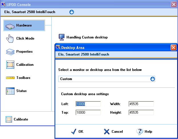
If
available in the desktop list, custom segments can also be defined to
associate a touch screen with a specific area of a desktop segment. A full
desktop calibration screen has a virtual co-ordinate size of 65535 x and y.
Custom calibration areas are based on these co-ordinate values. The example
below shows a custom calibration area where there is a 10000 co-ord boarder
such that calibration is restricted to a central area on the desktop:
Custom segment definition
Resultant custom segment calibration screen
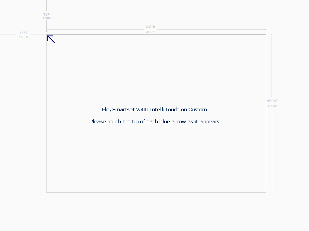
The
grey lines are not actually shown on the calibration screen but have been
superimposed to show the calculations used by the calibration procedure.
After touching each point (in this case the calibration pattern was set to 4
points, 0% margin) the touch area will be restricted to within the custom
area. Touches outside this area will be ignored. The calibration background
covers the entire desktop but the arrows )or crosses) are placed in accordance
with the defined custom area.
Starting
with UPDD build 5.0.2.469 custom desktop segments are supported on multiple
monitors.
To
use this feature set the setting MonitorNumberForSegment to identify the
monitor to be used.
NB
the monitor number is the UPDD monitor number, not the Windows number.
E.g.
tbutils
setting dw MonitorNumberForSegment 2
The
custom settings are set the same as for the primary monitor, even when the
resolutions differ the range to describe the whole monitor is 0 – 65535
·
Default
calibration settings
UPDD
can be supplied with default calibration data. This is particular useful in
complex configurations, especially when many toolbars are defined and UPDD is
being used on a preconfigured system. This allows for the display and the
toolbars to be calibrated ‘out the box’. See dump4tba
calibration option below for further details.
·
Raw
and Calibrated data description
The
driver can deliver, via the API, raw and calibrated touch data. Here is an explanation
of what is actually meant by these terms:
Raw data
Raw
touch data is data that is sent from the controller and received by the
driver - data in. This is data that has not been adjusted in any way
by the driver (other than to convert the bits in the data packet to x and y
values according to the protocol definition) and will represent co-ordinate
data sent by the controller covering the full physical touch area of the
touch screen. If the controller's firmware is also not adjusting the data in
any way then the data is in its total raw form. However, if the controller
has been hardware calibrated then the data will also be adjusted by the
firmware and in this sense is calibrated data (aligned to the video area)
delivered directly from the controller.
Calibrated data
This
is translated raw touch data that has been is manipulated by the driver and
delivered to the OS (to move the system pointer) and / or applications via
the UPDD API. This can be considered to be data that is output by the driver
- data out. A better term for this data may be normalised or adjusted
rather than calibrated as calibration is just one adjustment made to the
data. Other adjustments taken into consideration are the invert X and Y
settings, current rotation and calibration data etc.
Auto-calibrated mode
Even
if the touch coordinates have not been aligned or scaled to the video (known
as calibration) by calibration data recorded during a UPDD Calibration (or
predefined in the installation package) the driver will still apply some
adjustment to the data. The calibration will be calculated based on the
theoretical co-ordinate range of the controller (hopefully correctly defined
in UPDD!) and the invert X and Y settings as well as screen orientation. To
this end the touch screen could well be 'calibrated' after updd install and
without performing a UPDD calibration in that the cursor will move very close
to the point of touch.
Calibration testing
A
calibration test utility, UPDDdraw, is used to test devices in as much as it
will draw a line as the pointer moves around to show the calibration
accuracy. This is testing the route of the data from the device via the
hardware port, processed by the UPPD driver and then fed into the system’s
low level mouse interface. See the UPDD Draw and
Test utility document for further information.
Calibration pattern
templates
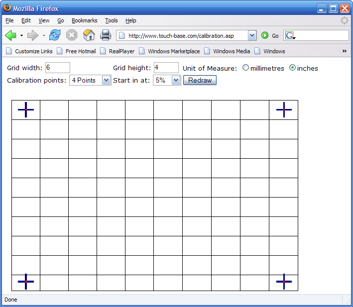
For
customers wishing to test touch hardware from a desktop (with the touch
screen remote from the video display) we have created a template generator. The
template combines the calibration pattern with the linearization grid. In the
generator you simply specify the size of the template in imperial or metric
dimensions, the number of calibration points and the % margin and request the
template be drawn. The template can then be printed to a suitable printer
(the browser printer driver or the printer should not attempt to rescale the
HTML drawing!).
The
following example shows a 6” x 4” template with 4 calibration points and a 5%
margin:
Calibration
parameters and User Interface calls
TBcalib
has a number of calibration related parameters and also offers a command line
interface to change various UPDD settings and can also be used to
reinitialise the controller or reactivate the driver.
The
calibration program exports this interface using the following syntax:
|
Windows
|
TBcalib
{parameter}
Note:
Entering the commands from a Windows command line would be tbcalib
“{parameters}”
|
|
Mac
OS X
|
5.x.x:
/Applications/Utilities/UPDD\ Calibration.app/Contents/MacOS/tbcalib
{parameter}
4.1.10:
/tbupddmx/tbcalib.app/Contents/MacOS/tbcalib {parameters}
|
|
Linux
|
/opt/tbupddlx/upddcalib
{parameter}
or
/opt/tbupddlx/tbcalib
{parameter}
This
command may need to be run prior to calling tbcalib:
export
LD_LIBRARY_PATH=/opt/tbupddlx:$LD_LIBRARY_PATH'
|
Notes:
1) If the parameter
affected has a space then the parameter value must be quoted, e.g. tbcalib
Device=0 "/setting:calibration beeps=0"
2) Win7 file write
issue:
Some of the user interface calls create files in the UPDD application folder
and under Windows 7 this folder may not have correct write permissions to
allow for files to be created. In this case you may see an error or you may
not find the file (it will be remapped elsewhere). When using functions that
create files ensure you have administration rights.
|
Calibration
parameters
|
Used
with the calibration procedure
|
|
None
passed
|
will
calibrate the first active device on the system.
|
|
Device=n
|
perform
request on the specified updd device and, if calibrating, the currently
selected calibration style, default first in list. Will also calibrate any
defined toolbars unless ‘Toolbar=ABogusValue’ is used to disable toolbar
processing.
Normally
used by calling programs to perform a given function against a specific
device, such as the UPDD Console device calibration option.
N=the
device handle of the device as held by UPDD. This option is used by UPDD
SDK based programs utilising the UPDD API to determine the device handle
using related API calls such as TBAPIGetRelativeDevice.
Controller
UPDD associated device handles can be listed by using the tbutils
list command.
|
|
Device=connected
|
Perform
request on the first connected device.
|
|
“Segment=segment
id”
(UPDD
ver 4.1.3 and above)
|
perform
request on the updd device associated with the updd desktop segment
identifier and, if calibrating, the currently selected calibration style,
default first in list. Will also calibrate any defined toolbars unless
‘Toolbar=ABogusValue’ is used to disable toolbar processing
Normally
used by calling programs to perform a given function against a specific
device, such as the UPDD Console device calibration option.
e.g.
Tbcalib “Segment=Monitor 2” /disable - would disable the updd device
associated with Monitor 2.
|
|
Toolbar=whatever
|
only
calibrate toolbar whatever
|
|
TOOLBAR
|
only
calibrate toolbars
|
|
Style=stylename
|
calibrates
a named style
|
|
/all
|
calibrates
all active devices. Prior to 4.1.8 1865, build this parameter also
calibrates any ‘calibratible’ toolbars. Post this version toolbars are not
calibrated.
|
|
/assignall
|
Automatically
associates a desktop (monitor) with the touch screen and performs
calibration. Cycles through all monitors. Very useful in multiple
touch monitor environments. See important note below in /configureall.
|
|
/configureall
|
Automatically
associates a desktop (monitor) with the touch screen. Cycles through all
monitors. Very useful in multiple
touch monitor environments.
Important
note:
Called from the UPDD Console, Desktop Area, Configure All option to
automatically configure desktop segments. Particularly useful in Window 7
systems where the monitor number shown to the user does not match the
internal display reference number exposed to applications and unknown by
end users. In XP and Vista these values are one of the same, not so in Win
7 !!!!! This option will set the desktop segment to that needed to
correctly address the monitor during calibration and system pointer
placement.
|
|
debug
|
Starting
with version 5.1.791 tbcalib supports a new option “debug”. When invoked
additional information is displayed on the calibration window.
For
example when touching the screen an indication of the number of accepted
samples (data packets) is shown:
Touching;
accepted 131 samples
If
using the setting “min cal delta” and a touch is too close to the previous
point this message is shown:
Too
close to previous point
|
|
User
Interface Calls
|
These
are now documented in a separate user interface
document
|
|
/screenresupdate
|
MAC
OS X only – Requests the driver to recalculate calibration mapping based
one the current screen resolution. To be used where a system is calibrated
in one resolution but uses other resolutions (especially useful where
applications are changing resolution)
|
|
Equivalent API call
|
DWORD nDevices;
TBApiGetSettingDWORD(0, _T("Number Of Devices"),
&nDevices);
for(unsigned j = 0; j < nDevices; ++j)
{
int dev=0;
dev = TBApiGetRelativeDevice(j);
if(!dev)
{
continue;
}
else
{
SetupForMultiMonitor(dev,this);
}
}
|
|
EEprom
|
|
|
eeprom
|
Retrieve
UPDD calibration data from controller EEPROM. For further details see EEPROM documentation. Will only work for controllers
that have eeprom calibration capabilities which is supported and enabled in
the driver.
|
|
eepromwrite
|
Write
the calibration data to eeprom. Typically used if an application has
calibrated using the calibration API’s and needs the updated data to be
transferred to eeprom.
|
|
System
calls
|
|
|
test
(see
also diag below)
(Win 7? – See note)
|
Captures
the raw data output from a device at each calibration point and saves it to
a log file, tbcalib.log. Useful in two circumstances:
1)
To show that data is being sent from a controller. The ‘touched’
calibration point will only be accepted if some data is received from the
controller.
2)
To analyse the data being generated from a controller. Especially useful
where no technical data is available for a controller that needs to be
configured for use by the UPDD driver. The log data can be used to help
configure the touch packet structure. For a USB device a special build of
the UPDD driver will be supplied that is configured with the USB Vendor and
Product id such that the UPDD driver is seen by the OS PnP manager as the
device driver. This option can then be used to capture the data packet
output from the device.
Important
notes
1)
The
test facility captures data being delivered from the com port or USB
device,Interface 0, endpoint 1. If no data is seen then it is likely that
either the device is not working, the device needs initializing before
touch data is generated, the device needs to be placed into a special mode
of operation or, for usb devices, the output is delivered on a different
interface or endpoint.
2)
If
executed on a multi monitor system only the first device is tested, or you
can pass Device=n to define a device.
3)
The
log file is written to the current directory so the user must have write
access
On a Windows systems ensure that you run the program as an administrator.
On non-windows systems ensure that you run the program from a writeable
directory, e.g. “~” (home).
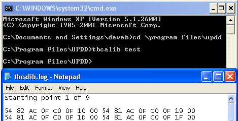
Windows
example
TBcalib
has been invoked from a command window (tbcalib test), invoking the test
option and has been run with 9 calibration points and the data stored in
the log file as shown:
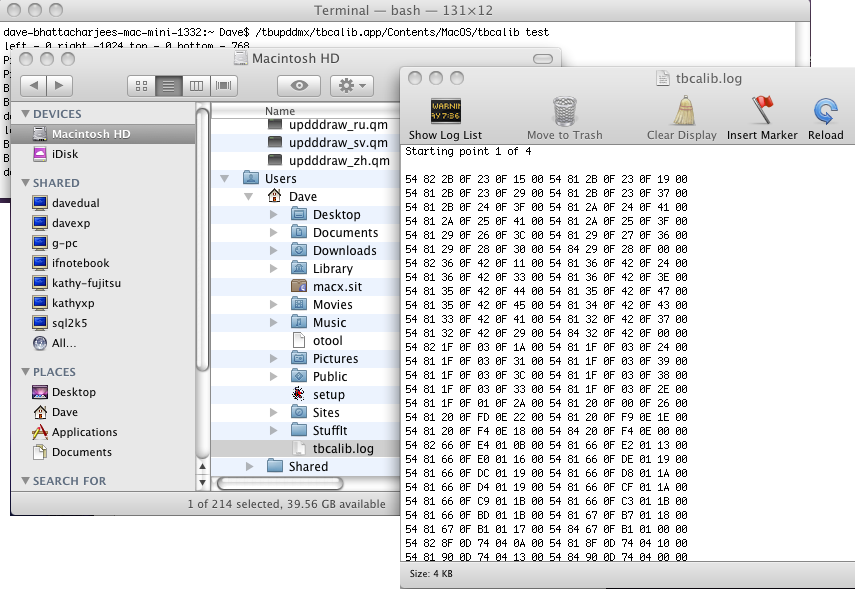
Mac OS X example
TBcalib
has been invoked from a terminal window
(/tbupddmx/tbcalib.app/Contents/MacOS/tbcalib test), invoking the test option
and has been run with 4 calibration points and the data stored in the log
file as shown:
|
|
diag
(see
also test above)
(Win 7? – See note)
|
Available
in 4.1.8, (build 1837 and above)
this option performs a similar option as the test option above and is
invoked in exactly the same way. However, the diag option requests a five stage touch sequence to be performed
so as to capture data to tbcalib.log file that is processed by our data
packet analysis tool.
Important
notes
1)
The
diag facility captures data being delivered from the com port or USB
device, interface 0, endpoint 1. If no data is seen then it is likely that
either the device is not working, the device needs initializing before
touch data is generated, the device needs to be placed into a special mode
of operation or, for usb devices, the output is delivered on a different
interface or endpoint.
2)
If
executed on a multi monitor system only the first device is tested, or you
can pass Device=n to define a device.
3)
The
log file is written to the current directory so the user must have write
access
On a Windows systems ensure that you run the program as an administrator.
On non-windows systems ensure that you run the program from a writeable
directory, e.g. “~” (home).
|
|
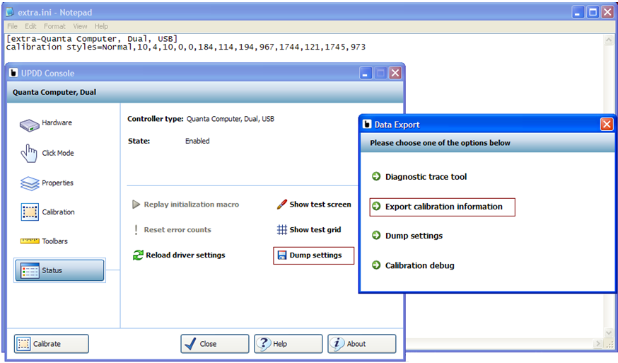
dump4tba
(Win 7? – See note)
|
This
option is used to create default calibration data from a calibrated
system. Since UPDD version 5.1.827 the data is written to a file
extra.ini. The data is written in a format suitable for embedding in our
software.
This
function respects the device=n option that can be passed to tbcalib and if
not specified selects the first device found
The
extra.ini file can be sent to touch-base for inclusion in your build or it
can be utilised by the setup program at the time setup is invoked. See Customised Settings
documentation.
The
log file is written to the current directory so the user must have write
access
On a Windows systems ensure that you run the program as an administrator.
On non-windows systems ensure that you run the program from a writeable
directory, e.g. “~” (home).
Since
5.1.1099 this feature can be invoked from the UPDD Console, Status screen
as shown below:
|
|
kernel
|
Available
in 4.1.8, (build 1784 and above)
enables minimal kernel mode touch that can be used to provide basic touch
functions until the standard, user mode, driver is available. This is
typically used in environments where the user mode driver (tbupddwu - which
runs as a Windows service) start up is delayed, such as sysprep or WinPE.
To
prepare for the kernel mode of operation, type this command on a system
that has only the device in question installed and execute the special two
point calibration that follows - this does not affect the current
calibration settings. This prepares the required registry
settings to be used in systems that require kernel mode to be enabled.
Under Vista or Windows 7 this command must be run from a user account that
has administrator privileges as it
needs to update the registry.
The
tbcalib kernel option prepares the registry settings required for this mode
of operation based on a controller with the co-ordinate origin (0,0) at the
top left and reporting x and y co-ordinates for horizontal and vertical
axis respectively. If the controller does not follow this form then one or
more manual changes to the created settings are required
1)
If moving
the touch in a vertical direction moves the cursor horizontally set swapxy
= 1 then repeat the test before setting the following items.
2)
If moving
the touch to the right moves the cursor left exchange the values of CalX0
& CalX1
3)
If moving
the touch downwards moves the cursor up exchange the values of CalY0 &
CalY1
Alternatively,
for 2 or 3 above, repeat the command and touch the opposite axis corners to
that requested. So, for example, if X axis is reversed, touch the top right
corner when requested to touch the top left and the bottom left when
requested to touch the bottom right.
|
Tbcalib
return codes
These are
the return codes from TBcalib and access to the code will be specific to the
launch method used:
|
0
|
Success
|
|
2
|
Calibration timed out
|
|
3
|
Escape
|
|
4
|
Syntax error passing parameter
|
|
5
|
Failure to open API
|
|
6
|
Couldn’t find a desktop segment
|
|
14
|
EEprom calibration read failure (e.g Checksum,
eeprom access etc)
|
|
24
|
If launched with “eeprom” argument and the eeprom
read succeeds but data is not in the expected format.
(This only applies to controllers using the latest
UPDD eeprom framework for calibration.)
|
In
addition to the above return codes 14 and 24 status are mapped into
tbupdd.ini setting “eepromreadstatus”, 0 = fail, 1 = success.
Contact
For
further information or technical assistance please email the technical
support team at technical@touch-base.com
|
