|
These
notes refer to the UPDD CE driver 5.1.x, and above, first released Aug 13.
This release supersedes version 4.1.10 and 4.0.6 which are no longer
supported.
Windows CE or Windows Embedded Compact are
embedded operating systems. For OEMs requiring a touch screen, or other
pointer interface on Windows CE devices, the Touch-Base Universal Pointer
Device Driver suite of software includes a 5.x, 6.x and 7.x CE driver.
With this release UPDD supports an
interface with the standard Windows CE GWES (Graphics, Windowing, and
Events Subsystem) touch interface. This allows for calibration via the built
in CE control panel Stylus option and provides an interface to the gesture
interface in Windows
CE 6.0 and later. The old ‘mouse’ interface is retained for testing purposes
and can also be used in situations whereby the GWES touch interface is not
part of the CE image.
This
UPDD version is built on the same software base as all other UPDD variants so
that most UPDD functions available on other platforms are now supported in
Windows CE (except for minor differences to
accommodate variance in the Windows CE implementation). Known
exceptions are listed in the limitation
section
below.
The
UPDD Application Program Interface is supported on Windows CE allowing 3rd
party utilities to be developed.
The main
differences between the new and previous driver are:
·
has
been implemented as a native CE touch device driver interfacing with the
standard Windows CE GWES touch interface
·
utilises
CE calibration procedure
·
supports
the native gesture interface introduced in Win CE 6
·
is
shipped with the new command line
utility
·
uses
the standard UPDD settings file
Development History
5.1.xx
was launched in August 2013 and development history is available here.
Hardware Interfaces
The driver mainly supports Serial and USB interfaces.
We have supported i2c but this interface is highly specialised and targeted
at specific controller chipsets.
USB has been tested on X86 and ARM
processors. If there are USB interface issues on other processors we may need
to be supplied a target system to investigate further and modify the UPDD USB
interface where applicable.
PS/2, supported since release 5.1.1246, has been
tested on X86 processors with a specific PS/2 touch device. There is no
guarantee this will work for all PS/2 devices. Currently CE7 only but
could be made available in other versions if required.
I2C has been tested on CE6 X86 only. Needs a
manual setting to be defined in the setting file.
Other interfaces could be added if required.
See important Port Interface issues below.
Processor support
The driver has been tested in house with X86 and ARM
CE. We can build drivers for other processors, as supported by the Microsoft
CE Platform Builder, on request.
At the time of writing, the processors supported by
UPDD in the various versions of CE are as follows:
|
|
Win CE version
|
Processor
|
|
|
5
|
X86, armv4i, mipsii, mipsii_fp,
mipsiv, mipsiv_fp, (for SH4 contact Touch-Base)
|
|
|
6
|
4.1.0 - X86, armv4i, mipsii, mipsii_fp,
mipsiv, mipsiv_fp, SH4
5.1.xx - X86, armv4i – Dec 2013 –
others can be made available on a per request basis
ARM note. Based on this article which states “The ARMV6 and
V7 architectures have enhanced cache designs which can improve the
performance of the Windows Embedded CE 6.0 kernel. The ARMV6 processor is
architecturally similar to the ARMV4I. The ARMV6 can run an OS image
targeted for the ARMV4I processor” there is a possibility that the armv4i
driver will run on ARMV6 architecture (ARM11 processors) – see also http://www.arm.com/community/software-enablement/microsoft/windows-embedded-ce.php, Architecture
Support tab.
|
|
|
7
|
X86,
armv5, armv6, armv7, mipsii, mipsii_fp
|
|
|
2013
|
X86,
ARM7 (please contact us if other builds are required)
|
More information on the CE product
range is available here:
http://www.microsoft.com/windowsembedded/en-us/develop/windows-embedded-products-for-developers.aspx
Any
system/processor can be supported as long as a Board Support Package is
available for the target processor. Read http://www.microsoft.com/windowsembedded/en-us/downloads/board-support-packages-for-windows-embedded.aspx
for
more information on BSP’s
Target
hardware may have to be supplied for testing if any problems are experienced
with the driver.
Important
note: Although we have built the CE components for the processors listed
above we can not test the driver on all supported processors due to lack of
target hardware. In theory the drivers should work on the target processor
as long as the component build process utilises the relevant BSP.
Software delivery
In this environment, UPDD is supplied as a number of
separate components. Software sent via email will be held in the file ZIP
file TBUPDDCE_n.n.n.ZIP where n.n.n is the release number.. Touch-Base
utilises virus detection software on all of our systems but recipients of the
software should pass the files through their own virus checking software
before proceeding with installation.
Normally a software package will be supplied with
just one touch controller supported in which case the settings
file
can be used as supplied, unless using a serial controller and the com port
needs to be changed via the autoinstalldevice setting. If the
software package contains more than one controller definition this setting is
also used to indicate the serial controller definition to use.
Components
The
UPDD CE package consists of the following components:
|
Component
|
Description
|
|
Logo.png
|
Suppliers
logo file – not used in this release but may be in future if a CE version
of UPDD Console is generated
|
|
Calib*.bmp
|
Corner
arrows calibration bitmaps. Crosshair bitmap embedded in calibration
program. (5.1.0 onwards)
|
|
tbupdd.bib
|
UPDD
Configuration file entries
|
|
tbupdd.dat
|
UPDD
System file entries
|
|
tbupdd.reg
|
UPDD
Registry file entries
|
|
tbupdd.ini
|
Driver and touch device settings
file.
|
|
tbapi.h
|
Header
file (Application Programming Interface – See **)
|
|
Processor sub
folder
|
UPDD
target processor related files: X86, ARMV4I, MIPS etc
|
|
upddce.dll
|
Native
CE touch driver.
|
|
tbupddceusb.dll
|
USB
interface. Not required for serial interface.
|
|
tbcalib.exe
|
Calibration
program. Can be used to calibrate in systems missing CE stylus
calibration.
|
|
tbutils.exe
|
Command line interface.
|
|
ace.dll
|
Inter
process communication library for the target processor
|
|
tbapi.dll/.lib
|
API
function calls (Application Programming Interface – See **)
|
|
**
Under CE the UPDD Application Programming Interface is implemented as a
Dynamic Link Library TBAPI.DLL/TBAPI.LIB and function declaration file
TBAPI.H. These are supplied with the driver but documented here
|
Requirements
The basic system
requirements for utilising UPDD are as follows:
·
Supported
CE version: 5, 6, 7 or 2103
·
Supported
processor version or one where a BSP program can be supplied. Alternatively
x86 based images can be run on a standard PC using the LOADCEPC utility.
·
Supported
touch controller
·
The
driver’s touch interface into CE is via GWES or standard mouse
port.
To utilize the native CE touch interface (GWES) and calibration utility the
target CE system must contain the touch screen CE
components.
If these components are not part of the image the ‘mouse’
interface is used.
·
The
driver requires access to TCP IP port 4141 for internal
computer processing only. Can be disabled if not using any UPDD API based
programs such as tbutils, tbcalib or any user written programs.
·
The
target system image must have been created with the appropriate platform
builder with any relevant system packs. We have had a customer report that
he was showing ‘crazy’ errors in the CE log file and identified the problem
as being a CE update applied to his Visual Studio 2005. He rolled back the
updates and the error disappeared!
For internal testing we build images with VS2005 with the relevant system
packs applied but with NO subsequent CE updates applied.
Specific embedded
or post install requirements are specified in the relevant section below.
UPDD version specific information
|
Release
|
Notes
|
|
1291
|
Starting with build 1291 Windows
CE now has a more comprehensive USB interface.
Whilst not all possible modes of
operation have been tried, this interface in theory offers support for most
features found in the UPDD desktop variants.
1) Multiple usb controllers
in a package.
2) Support for devices that
utilise multiple or non-zero interfaces.
3) Packet disposition support
4) Multiple monitor support
(only segments supported).
NB the one off “shadowed” monitor
support is not available in this build. It was a “one of” not compatible
with the current design, but could be easily re-added in the future if
required.
|
Using the components
The components
can either be installed on an existing CE system or embedded into a CE image
as detailed below.
Installing on existing image
Installing into
an already created image can be performed for two reasons, either to test /
demo the driver prior to embedding or as a permanent installation solution
whereby there is not an option to embed the driver into the desired image.
If installing the
driver for test or demo purposes then the driver can be installed,
tested/demoed and then discarded. However, if the installation is being used
to install the driver as a fully working solution this can only be achieved
on systems that have persistent storage for the file system and the registry
such that the changes to the system are retained over a reboot and available
during driver load.
These notes are
based on installing on a CE5 image that did not contain the touch stylus
components built into the image and therefore the driver was configured to
use the basic mouse interface to handle cursor movements and click.
Whether a post
installation is possible for a given system depends completely on the
architecture of that specific system and in some cases may simply not be
possible. However these notes can be used as a starting point to experiment.
As a minimum the
system will need:
1)
Persistent
disk storage, such as a flash drive or similar device.
2)
A
mechanism to save updates to the registry again typically on a flash device.
A customer reported using an image whereby the manufacturer of the board had
embedded a utility that periodically wrote any registry changes to the flash
drive.
3)
A
mechanism to load files onto the target system.
You will also
need a tool to edit the registry. One such editor is described here
http://geekswithblogs.net/BruceEitman/archive/2009/07/27/window-ce-simple-little-registry-editor.aspx
Without these
aspects the software will probably not work in a post installation scenario.
There may well be other dependencies which prevent this working so we cannot
guarantee that post installation will be successful and this will need to be
assessed on a case by case basis.
The steps to
follow are:
1)
Identify
the system path by examining
registry entry HKEY_LOCAL_MACHINE\Loader\SystemPath or
HKEY_LOCAL_MACHINE\Launch\SystemPath for the system path entry. This lists
the folders searched by the system for .dll or .exe files. Identify if one of
these folders is on your persistent storage device which can be used for the
driver modules and settings file or create a new folder and add its location
to this registry entry. If you need to add additional folder names to the
system path you will need a registry editor, such as ceregeditor or SLRE.
It is our understanding that most CE systems will have a SystemPath. However,
if this is not the case and you have to create one ensure the key is created
as type REG_MULTI_SZ.
2) The driver’s
touch interface into CE is via GWES or standard mouse port. The
GWES interface will only be available if the image was built for touch and
includes the Touch Screen
(Stylus) components.
If the touch component is not built into the image (the stylus calibration option in the control
panel will be missing) then enable the mouse
port interface.
3) Extract the
supplied updd files and copy to the target system by whatever means are
appropriate, copy to the folder described in Step 1 above. The files *.bib,
*.dat, *.h *.reg are not required on the target.
If copying over a previously installed UPDD driver then the system will
report certain UPDD files are in use and cannot be overwritten. Renaming the
file will allow another copy to be placed on the system – e.g. ‘ren
upddce.dll deleteme’ – which can then be deleted following the next reboot
and once the updates have been tested.
When extracting the driver software some files will be placed in a sub folder
that represents the processor type, i.e. X86. One customer implied that they
had issues when using the sub folder structure and placed all files in the
same folder. We did not experience any issues when using the sub folder
structure.
4) Replicate all the
registry setting entries in tbupdd.reg in to the registry on the device,
using a suitable registry editor, such as ceregeditor or SLRE.
5)
Create
a further registry setting to identify the full path to the driver’s settings file:
HKEY_LOCAL_MACHINE\Drivers\BuiltIn\updd\settings=<path to ini>.
e.g. \Hard Disk\System\tbupdd.ini (please note that the path must contain the
name of the file)
6)
Edit
tbupdd.ini changing the “updd folder” entry to reflect the location of the
calibration bitmap images.
Eg updd folder=\mydisk\myfolder\
Embedding
It is assumed
that the developer is using the appropriate Visual Studio, Platform Builder
and service packs to create the relevant Win CE image for the target
hardware.
The software is
supplied in a form to make it easy for users with little experience with
Windows CE to get up and running as quickly as possible. CE experts with
knowledge of the BIB structure are free to amend the configuration files as
required, so long as the embedded files are located in accessible locations
on the target and with the correct attributes.
For users
unfamiliar with Windows CE we suggest the following guides to creating a
Windows CE image.
http://msdn.microsoft.com/en-US/library/ee483161(v=WinEmbedded.60).aspx (CE 6 / 7)
http://msdn.microsoft.com/en-us/library/aa446910.aspx (CE5)
To incorporate the driver into your image follow these instructions:
1. Expand the
tbupddce.zip file. Some of the files are target specific, these target
specific files are shown by the black highlight in the example below (in this
case for the x86 target):
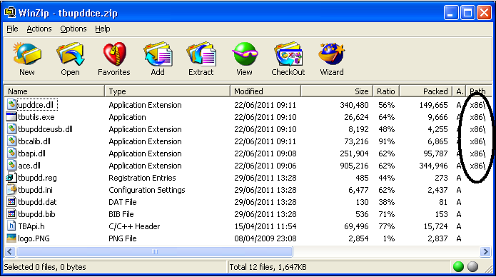
2. Copy the files
for your chosen target (processor) to the root folder of your build system
(typically c:\wince500, c:\wince600 or c:\wince700).
Also copy the file tbupdd.ini to the same location
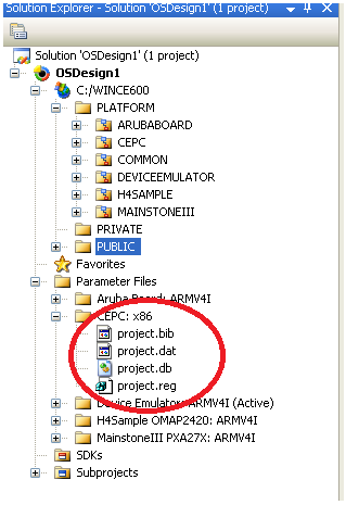
3. Locate
the files project.bib, project.reg and project.dat in your platform builder
(visual studio in CE 6.0 and later) project tree. Open the files tbupdd.bib,
tbupdd.reg and tbupdd.dat and copy / paste the contents at the bottom of the
corresponding project files
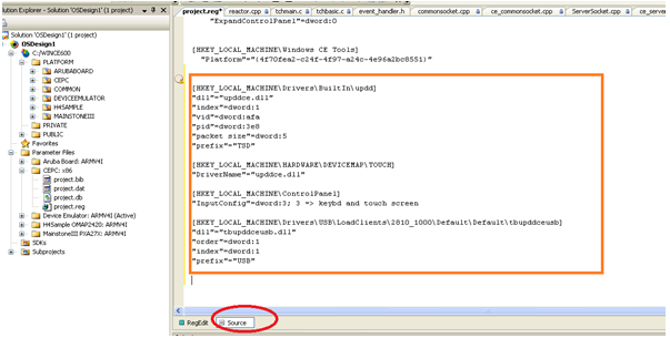
The following example shows the updd settings added to the project.reg file.
Note in this case the source tab is selected.
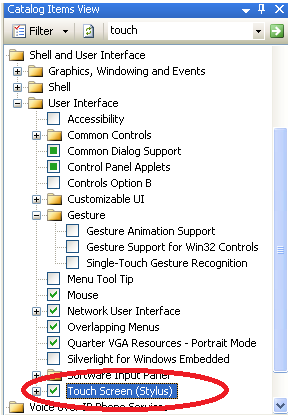
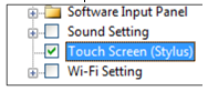
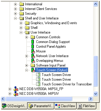
4. In order to utilize the native touch interface and
calibrate the screen via the stylus calibration option in the control panel
the Touch
Screen (Stylus) option is selected in the
design view / project catalog. If this component cannot be embedded it is
important to enable the mouse
interface.
This option enables stylus
functionality within the CE image. A certain
amount of input functionality, such as the Software-based
Input Panel, Handwriting Recognizer Engine
(HWX), and Transcriber Handwriting Recognizer Application Catalog items,
require the Touch Screen (Stylus) Catalog item. UPDD utilizes the control
panel Stylus option to perform calibration.
|
CE6 touch
stylus enable
|
CE5 touch stylus enable (see
important note below)
|
|
CE7 touch stylus enable
|
Important note: In our tests
this turned out not to work correctly. We circumvented this issue by making
the following change, which might be useful if a similar problem is
encountered.
1)
Open the file C:\WINCE500\PUBLIC\CEBASE\OAK\MISC\wceshellfe.bat
2)
Locate the line
if
"%__SYSGEN_TOUCH_CURSOR%"=="1" set
CPLMAIN_COMPONENTS=%CPLMAIN_COMPONENTS%
stylus
3)
Edit this line to read
set
CPLMAIN_COMPONENTS=%CPLMAIN_COMPONENTS% stylus
|
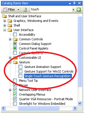
5. Gestures
Starting with CE version 6.0 Windows CE supports gesture functionality
allowing gestures from the touch-screen to be passed to applications that
support such gestures. This functionality can be enabled by selecting the
items shown below in the CE catalog. This functionality is part of GWES and
so cannot be used when in Mouse Mode is used. It is only useful when applications are in use
that supports this functionality.
In addition, WEC7 introduced support for dual touch and gestures that can
work with gesture aware applications. We added support for dual touch in
UPDD version 5.0.2 and further revised it in 5.1.0. This is only available
via the GWES interface if the appropriate settings have been enabled in the
image. The driver receives single and dual touch data from the touch device
and posts this to the GWES interface. As long as the controller output
characteristics are adequate (data rate, timely pen clicks, correct stylus
streams etc) then gestures should be correctly calculated and performed.
As documented: “Depending on your touch screen driver, Compact 7 supports
multi-touch gestures with two contact points, or dual-symmetrical gestures.
If your touch screen driver supports dual-symmetrical gestures, the gesture
engine will try to determine how the X and Y coordinates should be paired.
For both dual-touch symmetrical and multi-touch gestures, the gesture
recognizer designates one contact point as the primary contact and keeps
track of the distance between the primary contact and the secondary contact.
|
CE6 Gesture settings
|
WEC7 Gesture settings
|
|
|
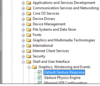
Enable the following
settings as required:
- Default
Gesture Response
- Gesture
Physics Engine
- Touch
Gesture GWES component
|
An
interesting article describing this functionality is available at
http://www.ptgsystems.com/blognet/post/2009/10/20/Touch-Gestures-and-the-Physics-Engine-in-Windows-Embedded-CE-60-R3.aspx
Another
comprehensive gesture article: http://blogs.msdn.com/b/marcpe/archive/2009/06/29/let-s-talk-about-touch-part1.aspx
Touch
gestures in WEC7 are further described here http://msdn.microsoft.com/en-us/library/ee499124.aspx and
caters for dual touch gestures.
A video
relating to WEC7 multi-touch is available here: http://www.microsoft.com/en-us/showcase/details.aspx?uuid=508dba11-4955-437f-abc0-3fef8ccd0b5b.
Updated gesture
support notes with UPDD 5.1.0 release
UPDD version 5.1.0 for Windows Compact Edition 7 introduces fully
tested support for the system dual touch interface.
WCE7 only supports dual touches; additional touches can be supported
using the UPDD API.
In
conjunction with WCE7 dual touch support WCE7 provides a gesture recognition
engine, it is important to note that this engine is intended to deliver
gesture information to 3rd party applications. As far as we are
aware there is no usage of this recogniser in the WCE7 shell or supplied
applications, so software has to be written by the system developer to
utilise these gestures.
There
may be a need to verify a WCE7 configuration that supports gestures without
writing addition software, for example to test the hardware implementation.
Note that UPDD passes data to the GWES component of WCE7 unchanged, therefore
the performance of the gesture solution is dependant for the most part on the
performance of the touch hardware and the implementation of the gesture
recogniser itself. We outline a procedure here which can be used to verify
how well these components perform with UPDD in use.
To
test your configuration use the Touch Driver Verification Tool described below.
6. Right
Click Processing
A "right click on hold" feature in Windows CE is provided by the
WinCE component AYGSHELL, as seen in this WEC7 setting:
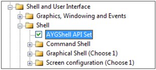
Windows CE generates this right click automatically when the left touch is
held stationary for a certain period of time. There is nothing that the
driver can currently do to influence this. If this component is present in a
Win CE image the right click on hold feature is enabled and you will see the
progress indicator if you hold a touch steady for a period of time.
When building an image AYGSHELL may or may not be included depending on your
requirements.
If installing the touch driver on an already created image you may or may not
have right click processing depending on the inclusion of AYGSHELL in the
image. If you do have right click processing and wish to disable or adjust
the right click threshold we are currently unaware of how this is achieved
but there are references on the web to a registry entry that can be used to
adjust the time “This amount of time can be controlled by the OEM through a
registry setting” but we’ve been unable to find it!
Further, this article http://msdn.microsoft.com/en-us/library/aa925176.aspx
implies that applications can specify if right click processing is enabled
within an application.
Having
followed the above instructions you should now be able to build and test your
CE image.
Additional
embedding notes:
1. Registry entries
·
If using a USB
device then one of the entries in the .reg settings refers to the device and
will contain the USB Vendor and Product ID values. The VID and PID values
MUST match the VID and PID of the controller in use, e.g. Controller has hex
VID = 1234 and PID = 11 values. Hex 1234 = decimal 4660 and Hex 11 = decimal 17. Based on this example the settings
would be as follows:
project.reg
[HKEY_LOCAL_MACHINE\Drivers\USB\LoadClients\4660_17\Default\Default\Tbupddceusb]
tbupdd.ini
[updd\parameters\1]
Product id=0x00000011
Vendor id=0x00001234
Important note: The files supplied should have the correct
vendor and product ids as they will have been generated for a touch device as
requested. If the values in the registry do not match the values of the usb
controller then request a driver that does match. If you manually change
these values to match then the driver will connect to the device. However,
the touch data generated is unlikely to match that as expected so it is
likely the touch will not work as expected.
·
Single controller
support: The registry
entries for a USB controller define a named USB device that is a placement
holder for the UPDD device and not a device that is actually used but must
exist, e.g.
[HKEY_LOCAL_MACHINE\Drivers\USB\LoadClients\4660_17\Default\Default\tbupddceusb]
"dll"="tbupddceusb.dll"
"order"=dword:1
"index"=dword:1 (this value should be defined such that it creates
a unique device name)
"prefix"="USB"
These default settings will reference a device USB1. If this is already
defined in the system change the index number to provide a unique name.
·
Multiple
controller support: To support
multiple controller types create one section in the usb\loadclients area as
below to define all the support controllers; e.g..
[HKEY_LOCAL_MACHINE\Drivers\USB\LoadClients\9103_1\Default\Default\tbupddceusb]
"dll"="tbupddceusb.dll"
"order"=dword:1
"index"=dword:1
"prefix"="USB"
[HKEY_LOCAL_MACHINE\Drivers\USB\LoadClients\9103_2\Default\Default\tbupddceusb2]
"dll"="tbupddceusb.dll"
"order"=dword:1"
“index"=dword:1
"prefix"="USB"
Notes
1. There is one identical section for each vid / pid combination.
2. The ini file section must be given a unique name: e.g. tbupddceusb2 in the
example above, when supporting devices of the same type (identical vid/pid)
3. CE does not provide any usb device "location" information.
Therefore we rely on the order in which the devices are notified at start up
to identify specific controllers. (We could use the serial number on a usb
device, but we have not as yet implemented this)
This should be reliable in a fixed system; but if devices are un / replugged
at run time the association might be lost.
4. If the devices have a different vid or pid or iProduct this will be used
to identify the device.
·
Ensure the InputConfig
entry is updated to indicate a touch screen is in use. For more information
on this setting see http://msdn.microsoft.com/en-us/library/ee482243.aspx
2. If, for any reason, the GWES component cannot be
utilised in the image then it is important to enable
the ‘mouse’ interface.
3.
Modify any settings in the UPDD settings file as required. See Driver Setting section below for more information.
4.
If system does not have persistent
registry or file system determine appropriate calibration strategy as described
in the calibrate section below.
5.
Make any
required software changes to the system components. See “Port interface issues” below.
6.
Ensure any calibration images in
use are held in the folder path as defined by the setting “updd folder”.
Since UPDD 5.1.1310 this setting defaults to the standard UPDD application
location.
Testing
One feature of the CE touch interface is that there
is no mouse cursor shown if the Touch Stylus has been enabled in the image.
This is by design as in a touch environment the visual feedback is at the
point of touch. If no cursor is present, the easiest and quickest test is to
touch on the CE desktop – when dragging on this screen a “wire frame” marker
is seen. This is particularly useful when working with an uncalibrated or
unattached touch screen.
There is also a touch verification utility for WEC7
when using the GWES interface called CETouchView, a standalone tool in the Windows Embedded Compact
Test Kit (CTK).
You can choose to run the CETouchView.exe on its own
for basic feedback or combined with the CETouchFilter.DLL which offers more
detailed information.
Using the CETouchFilter.DLL
Important note: In the current CETouchView documentation it
states you need to set up a registry entry DriverExName for the
CETouchFilter.dll in order to view both raw touch data and gesture messages.
In our testing we found this to be incorrect and the registry entry should be
named DriverName.
i.e.
[HKEY_LOCAL_MACHINE\HARDWARE\DEVICEMAP\TOUCH]
"DriverExName"="upddce.dll"
"DriverName"="CETouchFilter.dll"
In our tests we also discovered that to use the
CETouchFilter.dll this you must also make the following setting:
[HKEY_LOCAL_MACHINE\Drivers\BuiltIn\updd]
;"dll"="upddce.dll" (; = line is changed to a comment )
Further, although the instructions are comprehensive
they do omit the location of cetouchfilter.dll / cetouchview.exe
These are located at : $(_WINCEROOT) \public\COMMON\oak\target\
$(_CPUINDPATH)
e.g. C:\WINCE700\public\COMMON\oak\target\x86\debug
The tool is also available in source form at:
$(_WINCEROOT)
\public\COMMON\sdk\samples\CeTouchView\App
Which might provide a useful starting point for
developing a WCE7 gesture aware application.
You will also need the following entries in the
MODULES section of your BIB
MODULES
cetouchfilter.dll
$(_FLATRELEASEDIR)\cetouchfilter.dll NK SHK
cetouchview.exe
$(_FLATRELEASEDIR)\cetouchview.exe NK
You can use CETouchView to verify the raw touch data
and gesture messages generated by your device as seen in this screen shot:
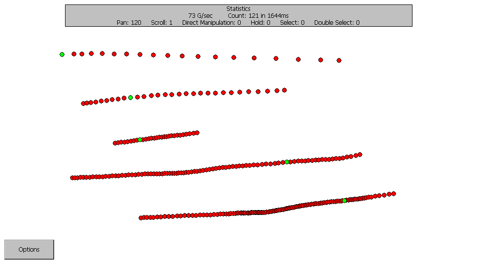
During our tests we found a few options quite useful:
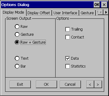
Setting the “Raw” option causes the program to draw a
single black line for each touch.
Setting “Gesture” causes the program to draw red
lines denoting gesture event positions when using a single touch and
additional detail when multiple touches are used.
“Trailing” causes the drawing and other information
to remain on the screen when no longer touching. Opening and closing the
options dialog is a useful way to clear the screen when this option is
selected.
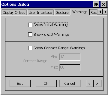
If running a debug build and you which to avoid the
debug assertions issued by the gesture recogniser it is helpful to turn off
all the warnings on this screen.
We found this video on the net that shows CETouchView in use on a
multi-touch system.
Calibration
The touch screen needs to be calibrated with the
desktop such that the point of touch generates a touch at the correct
position on the desktop. The calibration procedure generates touch
co-ordinate data that is associated with known positions on the desktop.
Using this data the driver can calculate the correct desktop position from
incoming touch co-ordinate data. This calibration data can be both generated
and utilised in a number of ways as discussed below. The method you select
will be dependent on your system’s configuration.
Irrespective of the calibration method used, in all
cases calibration data in tbupdd.ini is what the driver actually uses. Data
external to this file is loaded to tbupdd.ini to make the calibration
effective.
During calibration, whether it be via the built in CE
stylus option or using UPDD’s calibration routine calibration data is written:
1) To tbupdd.ini – always
2) To the registry(see note 1) – if the
general (see note 3) setting ceregcalibration(see note 2) is =
1 in tbupdd.ini
3) To eeprom - if the touch controller supports
eeprom storage and the device setting “eeprom calibration” = 1 in tbupdd.ini
When the driver loads calibration data is read:
1) From eeprom - if the registry setting
HKLM\Drivers\Builtin\updd\eepromreadatstart=1 (a DWORD value) (which invokes
command ‘tbcalib eeprom’ to read the eeprom).
2) From the registry(see note 1) - if the
device setting ceregcalibration(see note 2) = 1 in tbupdd.ini
Notes
Really important note: Prior to the initial
calibration of the device, the calibration is based on a 2 point, corner
calibration scaled to the co-ordinate touch range defined for the controller.
Only when a calibration is initiated is the calibration configuration defined
for the device copied to the active controller area in the .ini file (e.g.updd\parameters\1\calibration
styles\0) and utilised. In cases where the tbupdd.ini file is not in
persistent storage it is important that after the initial calibration the
tbutil.ini file is taken from the working system and re-embedded back in the
image. This is particularly important when using manual calibration.
1. Registry based calibration data is
held at HKLM\Drivers\Builtin\updd\calibration\001
Data is only saved when ceregcalibration=1
Data is only utilized when ceregcalibration=1
NB the data saved at HKLM\HARDWARE\DEVICEMAP\TOUCH\CalibrationData is saved
by the built in stylus function, it is NOT utilized by UPDD
2. ceregcalibration is a setting in the
file tbupdd.ini. It is a general setting, which means that it must be in the
general section; [updd\parameters]
3. Prior to build 1310 ceregcalibration
was a device specific setting. It has been made a general setting to simplify
setup.
CE systems usually have a single
embedded touch screen. Recently UPDD has started to add support for some
cases where multiple controllers are used.
The default calibration options
listed above however only work for the single controller case.
This support will be extended when /
If there is a wider need for multi controller support in Windows CE.
Calibration Options
Based on your requirements you may choose any
combination of the following calibration options to cater for calibration
within your system.
|
Option
|
Description
|
|
Manual
|
A
calibration procedure is invoked to show on-screen calibration points that
are touched to collect calibration data
|
|
|
CE
Stylus
|
Using
the build in stylus calibration function. A user invokes this function from
the control panel, stylus, calibration option. This method offers tight
integration with Windows CE. This is only available on systems built with
touch support enabled so is not suitable for “post installation” unless the
image already has touch support enabled. It is currently also restricted to
a 4 point calibration with a 10% margin.
|
|
|
UPDD
Calibration
|
Using the
UPDD calibration program. Tbcalib.exe provides most calibration features
available to the desktop based calibration software (apart from some custom
graphic features and eeprom support for some controllers. This module is
not integrated with CE (e.g. in the control panel) by default although of
course an integrator is free to adopt an appropriate integration strategy
to suit the target device.
|
|
Pre-defined
|
The
supplied UPDD settings file does not contain any calibration data so
devices are uncalibrated when first used. However, it is possible to place
good calibration data in the settings file such that the device is
calibrated following image creation or install.
|
|
EEPROM
storage
|
UPDD
data
|
Where
supported, caters for UPDD calibration data to be stored in the
controller’s eeprom and not dependant on any calibration data being
available on the CE system.
|
|
|
Hardware
based
|
Invokes
controller based calibration procedure – not supported in new driver but
will be available in a future release.
|
|
Registry Storage
|
Starting
with updd version 5.1.796 updd for Windows CE supports registry based
calibration.
This
allows integrators of systems with a persistent registry to utilise this
for storage of calibration data.
|
Manual Calibration
The native stylus
or UPDD calibration functions are invoked to perform manual calibration. An
implementation using manual calibration needs to decide on a strategy for
initiating the calibration procedure. E.g. executing the
calibration program at start-up or placing an icon on the desktop.
These and other
options are implemented via the platform configuration.
One option we are
considering is that the driver will automatically invoke the calibration
procedure at startup based on a system setting. This would be used in
environments where calibration was performed every time the system started.
Please contact us if this is required.
Native CE stylus
Once the image is running you can calibrate the touch
screen by using the Stylus option in the control panel. This is illustrated
below. Note that the exact screens vary according to the system
configuration.
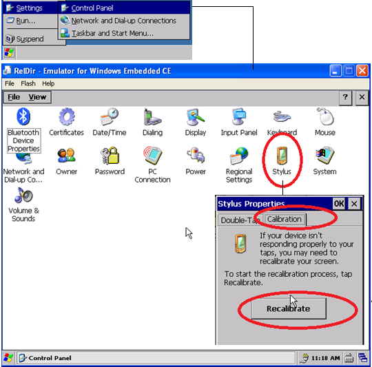
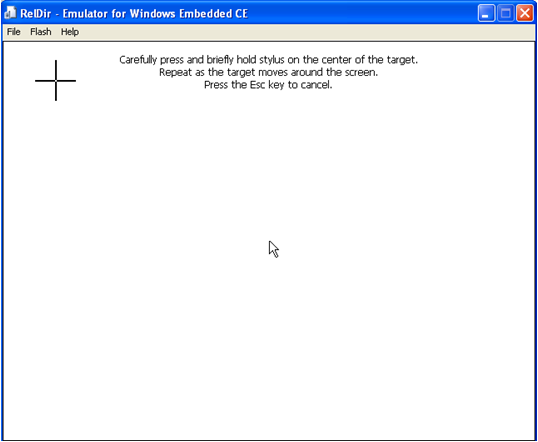
This will invoke the calibration procedure:
We understand that registry setting
HKLM\HARDWARE\DEVICEMAP\TOUCH\MaxCalError deals with how picky the touch
calibration application will be when you touch the calibration crosses.
Given that the
UPDD driver is a GWES conformant driver the native calibration calls the
SetCalibrationPoints function within our driver. The calibration data is
converted to the format used by UPDD and stored in the UPDD settings file.
If eeprom storage
is enabled and configured for UPDD data storage then the calibration data is
also written to eeprom.
If registry
storage is enabled then the data is also written to the registry.
Currently Stylus
calibration is only support for single device configurations.
We provide UPDD Calibration, see below, for
extended features when the built in stylus calibration is not sufficient. Multi
device support is one such case.
UPDD Calibration function
Once the image is running you can calibrate the touch
screen by using the TBcalib program. The number of calibration points used
and their position is dictated by the values in the tbupdd.ini file, branch
[updd\parameters\1\calibration styles\0.
In this example the number of calibration points has
been set to 5 points, no margin (0% - corner).
Note any changes to the number of calibration points must be reflected in the
number of cal and ref entries defined.
[updd\parameters\1\calibration styles\0]
calibration background=0x00000001
calibration points=0x00000005
calibration rotation=0x00000000
calibration start pct=0x00000000
calibration style=Normal
calibration timeout=0x0000000A
calx0=0x0000000F
calx1=0x00000010
calx2=0x000003BD
calx3=0x00000772
calx4=0x00000770
caly0=0x0000000D
caly1=0x00000425
caly2=0x0000021C
caly3=0x00000012
caly4=0x00000429
refx0=0x00000000
refx1=0x00000000
refx2=0x00007FFF
refx3=0x0000FFFF
refx4=0x0000FFFF
refy0=0x00000000
refy1=0x0000FFFF
refy2=0x00007FFF
refy3=0x00000000
refy4=0x0000FFFF
Following calibration, the new active calibration
data is always stored in the UPDD settings file at branch
[updd\parameters\1].
If eeprom storage is enabled and configured for UPDD
data storage then the calibration data is also written to eeprom.
If eeprom storage is enabled and configured for
hardware eeprom the associated hardware calibration procedure is performed
such that the controller scales the co-ordinate output accordingly.
If registry storage is enabled then the data is also
written to the registry
Note: Early versions of tbcalib had a dependency on a
graphic shell being part of the CE image. Since Nov 2013, build 5.1.???, this
dependency has been removed. With Win CE 2013 there is less emphasis on the
use of a graphical shell as discussed here: http://blogs.msdn.com/b/windows-embedded/archive/2013/08/06/creating-a-custom-shell-in-compact-2013.aspx
Pre-define
calibration data
In cases where neither
persistent storage (registry or file) nor EEPROM based calibration are
available the calibrated data can be embedded in the target image to
pre-calibrate the system. This approach is only suitable for systems where
the calibration data does not change significantly over time or with use.
To pre-calibrate the system:
TBUPDD.INI file
1)
Calibrate
normally
2)
From a
command prompt (cmd.exe) type “tbutils dump4tba”. – for more information see Command Line Interface document
3)
Open the file tbcalib.tba created by this process and copy the string
contained in it (if no file is created ensure you are running the program in
a writable folder and try again, e.g. /application/data/updd).
4)
Paste the
string into the calibration styles section for the controller replacing the
default info shown in red below. This is in the copy of tbupdd.ini in your
build environment:
[updd\parameters\controller\ts001]
....
calibration styles=Normal,n,n,n,n,n,n,n,n,n
5)
Adjust the following settings to cater for any calibration inversion
required:
[updd\parameters\controller\ts001]
invertx=0x00000000
inverty=0x00000000
swapxy=0x00000000
6) Rebuild the target image.
Registry Storage
Starting with updd version 5.1.796 (and further
updated in 5.1.1310) updd for Windows CE supports registry based calibration.
This allows integrators of systems with a persistent
registry to utilise this for storage of calibration data.
It also provides an alternate means by which default
calibration data can be proved on a system that does not have a persistent
registry.
To utilise registry run the command ‘tbutils nodevice
setting dw ceregcalibration 1’ after the system is loaded with the touch
plugged in but before calibration.
With the above setting defined then after a
calibration has been performed the Registry calibration data is held at:
HKEY_LOCAL_MACHINE\Drivers\BuiltIn\updd\calibration\N
Where N is the device handle for a specific device
(usually 001 on CE systems) naming a REG_SZ value with the following format
<npoints>,<style>,<rotation when
calibrated>,<swapxy>,<margin>,<calx0>,<caly0>,
…. <calxn>,<calyn>
To embed this data in a target system the easiest
approach is to calibrate a working system and simply copy the value of this
key to your .reg file and re-embed the tbupdd.ini file taken from the same
system.
It is important to take both the registry setting and
the tbupdd.ini file back to the image because the calibration data held in
the registry is associated with the updd device entry and its defined
calibration criteria (percentage margin, no of calibration points etc) in the
UPDD settings file. The UPDD device entry is created at the time the touch
device is first discovered. Assuming you are implementing registry storage
because the setting file is not held in persistent storage then it is
important to take a copy of the setting file after the initial calibration so
that the captured registry calibration data matches the calibration criteria
held in the settings file.
Therefore the procedure for setting up register
calibration is as follows:
1.
On the embedded
image Open a command windows with start -> run -> cmd.
2.
Locate and run
the command ‘TButils nodevice setting dw ceregcalibration 1’
Prior to build 1310 ceregcalibration was a device specific setting. It has
been made a general setting to simplify setup.
3.
Perform the
calibration.
4.
Take the registry
setting calibration data and place in your .reg file.
5.
Take a copy of
/application/updd/tbupdd.ini from the target system and re-embed this in your
image replacing the supplied tbupdd.ini file.
This way the captured registry data matches the
calibration configuration for the device held in the settings file.
Note: The native
calibration procedure will also store calibration co-ordinates in the
registry at HKEY_LOCAL_MACHINE\Hardware\DeviceMap\Touch\CalibrationData. E,g.
[HKEY_LOCAL_MACHINE\HARDWARE\DEVICEMAP\TOUCH]
"CalibrationData"="585,628 541,3562 3527,599 3524,3550 "
This is not held
in a format that can be utilised by the driver hence the registry
implementation is as documented above.
EEPROM Storage
Some controllers support the saving of calibration
data in persistent memory (eeprom) on the controller itself. Subject to the
controller supporting this feature and UPDD implementing
EEPROM support for the specific device then calibration data can be saved on the device.
If the UPDD setting file has an entry ‘eeprom
protocol = ‘protocol id’ then this indicates that updd supports eeprom
storage for the touch controller but it does not necessarily indicate if this
is supported in CE due to differences in the CE platform. See EEprom
documentation for more
information about supported controllers under CE.
For supported controllers simply set the eeprom
calibration option in tbupdd.ini to 1
[updd\parameters\controller\ts001]
eeprom
calibration=0x1
eeprom
protocol=’protocol id’ – This is the protocol id
used by the driver to support eeprom in the controller.
For
the eeprom data to be read from the device automatically at startup the
following registry setting must also be set; eepromreadatstart=1; e.g.:-
[HKEY_LOCAL_MACHINE\Drivers\BuiltIn\updd]
" eepromreadatstart "= dword:1
Important Note, reading the eeprom data at startup
loads an additional module (tbcalib.exe) into kernel memory so in some cases
the memory mapping layout of the image may need to change. We most often see
this in debug images. If enabling this option leads to a crash in tbcalib at
startup this is very likely the cause.
For hardware based eeprom calibration (where
supported) the controller’s coordinate touch data will be scaled accordingly.
Calibration
persistence
A common issue with CE devices is saving calibration
data when the device is reset or restarted. There are three possibly choices
available depending on the touch controller hardware and the setup of the CE
device.
The driver will utilize, in preference of order, EEprom (if enabled),
registry (if calibration data exists) and TBUPDD.INI file calibration data.
In the case of eeprom or registry storage the calibration data is accessed
and then stored in the tbupdd.ini file such that this file will always
contain the current calibration data. It is up to the system integrator to
ensure that which every method is used there is valid calibration data
available.
1) Registry storage. If utilising UPDD registry storage
the data is read from the registry and stored in the UPDD settings file.
2) EEPROM storage. Subject to the controller supporting
this feature and UPDD implementing support for the specific device
calibration data can be saved on the device. The calibration data is read
from eeprom and stored in the UPDD settings file
3) File system storage. Irrespective of calibration
utility used (Stylus or tbcalib based calibration) the calibration data is
stored in the driver’s setting file tbupdd.ini. If the file is in persistent
storage then the calibration data held there will be saved across a system
restart. If the file is placed in a different location to that expected by
the driver this setting can be used to specify the alternate location. Note, if both
registry and file based calibration data is available the driver will utilise
the registry based data although the data will be written to both locations.
Unless the target system has persistent storage for
the registry, or the file system holding tbupdd.ini, or eeprom storage is
used then calibration data will not be saved across a reboot.
If persistent storage is available for the tbupdd.ini
or registry file then no further action is required. In the case that a
persistent registry is available the software saves the calibration data to
the registry and this data is written to tbupdd.ini at startup.
However, if calibration data is not held in permanent
or non-volatile memory then additional calibration options, such as pre-calibration, should be considered.
Calibration
beeps
Calibration beep option to be investigated and
not currently available. Please contact Touch-Base should this be required.
Calling calibration from an application
This section to
be confirmed as is untested and speculation only. It has been copied from an
article on the internet…
Sometimes it may
be necessary to cause a touch calibration to occur from an application,
perhaps because of drift or because the initial values as set during the
production process weren’t quite right.
This is fairly
straightforward to achieve as the relevant method is exposed by coredll.dll
All that is
needed is to declare a platform invoke (P/Invoke) to the coredll.dll method, which can then be called from within
application code:
A C# compact
framework example would be:
using System;
using
System.Runtime.InteropServices;
namespace
DynamicDevices.Utilities
{
///
/// Expose
'coredll' native methods
///
public class
NativeMethods
{
[DllImport("coredll.dll")]
public
static extern void TouchCalibrate();
}
}
Rotate
The current version of the driver supports operation
in a fixed rotated mode. All that is required is to calibrate in the desired
rotation (as long as your system’s display driver supports rotation).
The following articles discuss Win CE rotation
Win CE 5 - http://msdn.microsoft.com/en-us/library/ms914404.aspx describes how to set Portrait mode as default if
required
Win CE 6 –
http://msdn.microsoft.com/en-us/library/ee499095%28v=winembedded.60%29.aspx
http://msdn.microsoft.com/en-us/library/ee485865%28v=winembedded.60%29.aspx
Win CE 7 -
http://msdn.microsoft.com/en-us/library/ee505713.aspx
Dynamic rotation is not yet supported. Given that
GWES is used and is responsible for rotation it is possible that this will
also just work, but this is subject to confirmation.
Typically, the rotate will be set in the registry,
such as this example for portrait mode:
HKEY_LOCAL_MACHINE\System\GDI\Rotation\"Angle"=dword:10e.
After the system has rotated we suggest that you
calibrate the touchscreen and then take the driver’s settings file tbupdd.ini
(e.g. /application support/updd/tbupdd.ini) from the target and embed this
file in your image and reboot.
TBcalib
size optimisation
Starting with UPDD
version 5.1.0 the Windows CE version of the calibration utility tbcalib.exe
has been optimised for size.
In order to reduce the image to the smallest possible
size the calibration target images are held externally.
These notes refer to build 5.1.792 and above and supports calibration with
additional visual feedback as described here.
The system integrator should choose which files to
embed and include these in the target at /application data/updd
The exact method for doing this up to the choice of
the integrator. The default UPDD configuration files shipped with UPDD
implement an example method using upddce.bib and upddce.dat.
In this default configuration only the files required
for a calibration margin >= 5% are included. The others are present as
comments.
The comments in these files describe the usage and
are repeated here
upddce.dat
;; image files for calibration margin >= 5% with
visual feedback
;; note _cr_ means cross
Directory("\application
data\updd"):-File("calib_cr_32_1.bmp","\Windows\calib_cr_32_1.bmp")
Directory("\application
data\updd"):-File("calib_cr_32_2.bmp","\Windows\calib_cr_32_2.bmp")
Directory("\application
data\updd"):-File("calib_cr_32_3.bmp","\Windows\calib_cr_32_3.bmp")
;; image files for calibration margin < 5%
;; note not all files are used for all styles so is
for example a 4 point calibration is required
;; only bl/tr/tl/br (bottom left, top right
etc) images are required
;Directory("\application
data\updd"):-File("calibbl_32_n_p.bmp","\Windows\calibbl_32_n_p.bmp")
;Directory("\application
data\updd"):-File("calibbr_32_n_p.bmp","\Windows\calibbr_32_n_p.bmp")
;Directory("\application
data\updd"):-File("calibb_32_n_p.bmp","\Windows\calibb_32_n_p.bmp")
;Directory("\application
data\updd"):-File("calibl_32_n_p.bmp","\Windows\calibl_32_n_p.bmp")
;Directory("\application
data\updd"):-File("calibr_32_n_p.bmp","\Windows\calibr_32_n_p.bmp")
;Directory("\application
data\updd"):-File("calibtl_32_n_p.bmp","\Windows\calibtl_32_n_p.bmp")
;Directory("\application
data\updd"):-File("calibtr_32_n_p.bmp","\Windows\calibtr_32_n_p.bmp")
;Directory("\application
data\updd"):-File("calibt_32_n_p.bmp","\Windows\calibt_32_n_p.bmp")
;Directory("\application data\updd"):-File("calib_cr_32_n_p.bmp","\Windows\calib_cr_32_n_p.bmp")
tbupdd.bib
;; see upddce.dat for a description of these files
calib_cr_32_1.bmp $(_WINCEROOT)\calib_cr_32_1.bmp
calib_cr_32_2.bmp $(_WINCEROOT)\calib_cr_32_2.bmp
calib_cr_32_3.bmp $(_WINCEROOT)\calib_cr_32_3.bmp
;calibbl_32_n_p.bmp $(_WINCEROOT)\calibbl_32_n_p.bmp
;calibbr_32_n_p.bmp $(_WINCEROOT)\calibbr_32_n_p.bmp
;calibb_32_n_p.bmp $(_WINCEROOT)\calibb_32_n_p.bmp
;calibl_32_n_p.bmp $(_WINCEROOT)\calibl_32_n_p.bmp
;calibr_32_n_p.bmp $(_WINCEROOT)\calibr_32_n_p.bmp
;calibtl_32_n_p.bmp $(_WINCEROOT)\calibtl_32_n_p.bmp
;calibtr_32_n_p.bmp $(_WINCEROOT)\calibtr_32_n_p.bmp
;calibt_32_n_p.bmp $(_WINCEROOT)\calibt_32_n_p.bmp
;calib_cr_32_n_p.bmp
$(_WINCEROOT)\calib_cr_32_n_p.bmp
You can of course implement your own icons as long as
you follow these guidelines:
1)
Use the Windows
BMP format.
2)
Use a fixed size
of 32 x 32 pixels.
3)
Ensure the
“hotspot” (the point of intended contact, a red dot in the default icons) is
in the same pixel location.
At the time of writing tbcalib on Windows CE does not
support other bitmap based operation on Windows CE, such as custom dialogs
for toolbars.
Invoking calibration at
system startup
Should this be required then this link appears to describe how this can be achieved.
Driver settings and general notes
The driver’s settings are located in the UPDD settings file and will usually be set to the default settings for the
controller in use. These settings are defined as part of generating the CE
driver for a given touch screen device.
For CE it is really important to understand that there
are default settings held in the setting file that are used to create a group
of setting for an active controller discovered on the system. This means that
there are two areas, default and active, in the settings file that hold
settings for a device. The setting file as delivered has a number of
sections but the default settings for a device are held at [updd\parameters\controller\ts001] (assuming one
device supported in the package). When a device is discovered in the system a
copy of the settings at this location are copied to [updd\parameters\1] or
[updd\parameters\2] for a 2nd device and so on.
To change a
controller setting prior to embedding the setting should be
changed in the [updd\parameters\controller\ts001] default setting branch. To
change a setting after embedding for the active device it
should be changed in the [updd\parameters\N] active setting branch using the tbutils command line interface.
Given that all settings for an embedded system are defined in the CE
Platform Builder and the image then embedded on the target image it has been
decided that there is no need for a UPDD CE GUI as settings in these
environments are locked down and in most cases the supplied configuration
file will contain the required device and driver settings. If this is not the
case then settings can be manually edited in the settings file as required.
We also offer a command line interface utility that can be used to change settings on the fly.
When embedding
there will be two copies of tbupdd.ini on the CE target system, the location
of which is dictated by the contents of the tbupdd.dat file.
\windows\tbupdd.ini
or \Windows\tbupdd.ini.orig (Oct 11 onwards)
\application
data\updd\tbupdd.ini
This is because
the BIB script creates the first entry and the DAT script then creates the
second real working entry.
By default the software use the settings file in
\application data\updd\tbupdd.ini
The example
tbupdd.dat places a copy of the read only file from the image
(\windows\tbupdd.ini) in this location.
If you need to
place the file in a different location, typically to utilise persistant
storage then define
the following registry entry:
HKEY_LOCAL_MACHINE\Drivers\BuiltIn\updd\settings=<path
to ini> ; full path to tbupdd.ini
e.g.
\Hard Disk\System\tbupdd.ini (please note that the path must contain the
name of the file)
If
implementing persistant storage remove the tbupdd.dat file entries and use a
means appropriate to your target to place a copy of tbudd.ini in the desired
location upon first usage. As persistant storage requires custom changes to
your image generic guidance cannot be given for this step.
The
file \windows\tbupdd.ini is only used in the example to be copied to the
writeable ram disk location in default configurations and can be omitted in a
production system that implements an alternate means to install this file.
Pre Oct 11 - We did not find a method to eliminate
the \windows copy. The redundant copy can be ignored and in any case is very
small.
Post Oct 11 - We determined it is not possible to
delete the \windows copy so we now copy the file to \Windows\tbupdd.ini.orig
and this is in turn copied to the active area. This is handled by the .dat
file so no user action is required.
Disable
access to TCP/IP port
UPDD API based programs communicate to the driver via
local port 4141. If you are not using any API based programs, such as
tbcalib, tbutils or any user written API program then access to the port can
be disabled as follows:
[updd\parameters] <- after this line
port=0x00000000
Incorrect
screen dimension issues
The driver utilises GetSystemMetrics() to determine
the logical (pixel) size of the screen. In some cases we see that this API
gives unexpected information (For example with a custom BSP in conjunction
with screen rotation). In this case the following entries in tbupdd.ini can
be used to override the system supplied settings. These values if set these
are always used in preference to the system supplied settings.
[updd\parameters] <- after this line
"ScreenWidth"=dword:00000320
"ScreenHeight"=dword:00000258
Change the hexadecimal value of these keys to reflect the resolution of the
screen. In the above example it is for an 800x600 screen (320 x 258
hexadecimal).
Touch interface via mouse port
The driver’s
touch interface into CE is via GWES or standard mouse port. The
GWES interface will only be available if the image was built for touch and
includes the Touch Screen
(Stylus) components.
If the touch
component is not built into the image (the stylus calibration option in the control panel will be missing) then enable the mouse port interface as follows:
1. Edit the supplied settings file tbupdd.ini to add
these entries:
(With UPDD 4.1.0 update both locations, in 5.1.0 only one need be defined)
[updd] <- after this line
cesendinput=0x00000001 <- add this entry or amend if it is already defined
[updd\parameters] <- after this line
cesendinput=0x00000001 <- add this entry or amend if it is already defined
This setting instructs the driver to use the standard mouse interface and
might not be necessary if the system supports a GWES touch interface. If
unsure try with and without this setting.
2. Uncomment ( remove the ; at the beginning of the
line) the following lines when using the mouse port interface:
[HKEY_LOCAL_MACHINE\Drivers\BuiltIn\updd]
;"dll"="upddce.dll"
;"priority"=dword:ff
"index"=dword:1
"vid"=dword:238f
(not required in 1291 and above)
"pid"=dword:1 (not required in 1291 and above)
"packet size"=dword:7(not required in 1291 and above)
"prefix"="TSD"
The release system will continue to set these
values for backward compatibility for the time being.
Serial port device and com port issues
Device and port definition
The
setting autoinstalldevice is used to direct the installation of the
device through the UPDD PNP manager. For USB devices this is handled
automatically but for serial devices this setting is used to select the
required serial device and specify the com port, even when only one is
configured in the software package.
This setting is
described below.
Example
[updd\parameters]
autoinstalldevice=1;Microchip,
AR1100, Serial;;COM1
Description
autoinstalldevice is comprised of several fields
separated by the “;” symbol as described below:
Note, prior to UPDD
build 5.1.1310 the “¬” character was used as a separator. This may still be
used if preferred. Automatically generated files retain the “¬” character for
backward compatability.
1)
The controller
id. Usually 1. This tells the PnP manager which TSNNN (default controller
settings – one per supported controller in the settings file) entry to select
during installation of the device. This value should not be changed unless
you have a software package with multiple controllers and you wish to select
a controller other than the first defined for installation. E.g. to select
TS003 set this to 3.
2)
The name with
which the device will be installed. This can be freely edited.
3)
Unused (needed
for compatibility with the standard updd installer).
4)
The
COM port. This can be edited as required. This is the com port that will
be selected when the device is installed. See important Port Interface issues below when defining serial ports.
Stop bit
definition
As of the driver issued Aug 2012 the stop bit
definition in the UPDD setting file has changed such that the entry
StopBits=0x0000000N defines the stop bit usage as follows, where N =:
1 = ONESTOPBIT
2 = TWOSTOPBITS
3 = ONE5STOPBITS (1.5)
Prior to this date the driver interpreted these
settings differently, 0 = 1, 1 = 1.5 and 2 = 2.
Important note:
For single device
definitions, when defining a serial device it is important that you do not
define the USB settings in the registry as this will prevent touch working in
serial mode. USB is considered configured if the vid is defined in the
registry
[HKEY_LOCAL_MACHINE\Drivers\BuiltIn\updd]
;"vid"=dword:nnnn
It should not be
defined or commented out as in the example above.
Multi-device
definitions that include both serial and USB devices are covered separately here.
Serial port close delay setting
The driver will
re-establish all interfaces when the TBAPIApply or TBAPIReloadNoApply API is
called. This is called at various times, such a when a setting is changed
using TButils, or when running other UPDD utility programs, such as
calibration. When using serial devices this will result in the closing and
immediate opening of a serial port connection. However, on a particular CE5
system it was discovered that the close could take a period of time to
complete so the subsequent open request was failing; indicating port was not
closed resulting in all sorts of strange effects when dealing with serially
connected devices.
In UPDD 5.1.780 we introduced a device setting, cepauseafterclose that can be
used to specify a wait time after closing a serial port to allow time for the
close to complete. On this particular system a 200ms delay overcame the issues
i.e. cepauseafterclose=0xc8.
PS/2 port device
This interface is
currently only supported in CE7 – please contact if required in other
versions.
Device
and port definition
The
setting autoinstalldevice is used to direct the installation of the device
through the UPDD PNP manager. For USB devices this is handled automatically
but for PS/2 devices this setting is used to select the required PS/2 device,
even when only one is configured in the software package.
This setting is
described below.
Example
[updd\parameters]
autoinstalldevice=1¬Microchip
PS/2¬¬PS2
Description
autoinstalldevice
is comprised of several fields separated by the “¬” symbol as described
below:
1.
The controller
id. Usually 1. This tells the PnP manager which TSNNN (default controller
settings – one per supported controller in the settings file) entry to select
during installation of the device. This value should not be changed unless
you have a software package with multiple controllers and you wish to select
a controller other than the first defined for installation. E.g. to select
TS003 set this to 3.
2.
The name with
which the device will be installed. This can be freely edited.
3.
Unused (needed
for compatibility with the standard updd installer).
4.
Indicates it’s a
PS/2 port interface.
I2C interface
To configure this
interface you need to manually update the port type in the settings file
thus:
[updd\parameters\1]
PortType=0x00000004
The current
implementation uses a I2C proxy driver, which must be loaded, and you need to
define the Port value to a valid value for the proxy driver. In the system we
used to develop the I2C interface the port value was set to “I2C1”. We
believe that an I2C interface will be very implementation specific and the
driver may need tailoring to the specific utilisation of the I2C interface.
Please contact us to discuss further.
Sound
Not currently
supported in the new driver. Please contact us should this be required.
Mouse Mode
As standard the GWES touch interface does not utilize
the mouse cursor therefore there is no mouse cursor movement when touching
the screen. In fact, when using the touch interface the mouse cursor becomes
invisible. For test purposes, during the development of the new native touch
interface we retained the previous mouse interface (which utilises the
SendInputAPI) and this can be enabled if mouse emulation (and therefore mouse
cursor movement) is required. It should be noted that operating systems are
moving away from the system cursor when utilising touch and we believe more end
users should be encouraged to use touch without the traditional mouse cursor
utilized for visual placement feedback. Mouse cursor is Mouse interface,
other or no visual feedback is Touch.
However, should you wish to see mouse cursor movement
then the following UPDD setting will enable the old mouse interface:
[updd\parameters]
cesendinput=0x00000001
It should be noted that any touch functionality built
into the OS which is enabled when touch input is processed via the GWES touch
interface will be lost if the touch data is passed via the mouse interface.
This is likely to be more relevant to Windows Compact (CE 7) than pre CE 7
versions.
We believe that for mouse mode to work you will need
to configure the Mouse Catalog in your CE image.
Multi-processor
considerations
Windows Compact Edition 7 supports SMP (Symmetric
multi-processor) systems. Until recently all CE systems have utilised a
single processor core and updd has been tested on such systems.
The core UPDD driver software runs on a number of
systems and is known to be stable on multi processor systems.
However we have been advised by a customer that on
SMP systems problems can occur.
Until such time as we can reproduce this issue we
have implemented a solution to run all UPDD threads on a single core.
To utilise this new feature set a registry DWORD
value at
HKEY_LOCAL_MACHINE\Drivers\BuiltIn\updd\affinity
The value specified is the processor number to be
used, we understand that this is a number from 0 – n-1 where n is the number
of processors available.
Priority
levels
In order to
provide adequate performance it is necessary for the driver to execute at a
higher priority than other active processes. In particular the explorer
component consumes a lot of CPU in some cases, so dragging items on the
desktop can be slowed. By default all critical threads in the driver execute
at priority level 249 (Hex FA) which gives good results in most cases (which
was the same as the HID mouse).
Should you wish
to alter this priority for any reason you can change the following settings.
For the main
driver (upddce.dll) add the Priority setting in tbupdd.ini setting in the
[updd] section.
[updd]
....
priority=0x000000FA
<change as required
For the USB
interface component (tbupddceusb.dll) add the registry setting
[HKEY_LOCAL_MACHINE\Drivers\BuiltIn\updd]
"priority"=dword:fa
<change as required
Module
size and ram usage
The tbupdd.bib
specifies that all modules/files are loaded:
MODULES
Approx size KB
upddce.dll
$(_WINCEROOT)\upddce.dll NK SHK 324K
tbapi.dll
$(_WINCEROOT)\tbapi.dll NK 72K
k.tbapi.dll $(_WINCEROOT)\tbapi.dll
NK SK
tbupddceusb.dll
$(_WINCEROOT)\tbupddceusb.dll NK SHK 10K
tbcalib.exe
$(_WINCEROOT)\tbcalib.exe NK 132K
tbutils.exe
$(_WINCEROOT)\tbutils.exe NK 30K
ace.dll
$(_WINCEROOT)\ace.dll NK 905K
k.ace.dll
$(_WINCEROOT)\ace.dll NK SK
FILES
tbupdd.ini.orig
$(_WINCEROOT)\tbupdd.ini NK
The ACE and TBAPI
files are loaded in both user and kernel space and the user space version may
not be required if the utilities, such as tbutils and tbcalib, are not being
utilised in which case they can be excluded from the tbupdd.bib file. When using
serial devices the tbupddceusb.dll can also be excluded.
Excluding these
modules is subject to verification within your own image.
Touch
packet data rate
In years gone by
it had been observed on some lower end systems that if all the incoming data
packets from fast touch controllers are processed it can have a detrimental
effect on the performance of the system. By default the driver processes
100% of the packets. This percentage can be adjusted by the UPDD setting
[updd\Parameters\1\]:SampleRate.
Changing the
setting from 64hex (100 dec) to 32hex (50 dec) indicates to process 50% of
incoming packets.
Multi-monitor / controller support
Windows CE does not support multiple monitors but
video splitters can be used to run multiple monitors in mirrored mode or
extended mode.
We have implemented support for multi monitor
configurations in a number of ways:
UPDD 4.1.10
UPDD will support a configuration where 2 or more
monitor and associated touch-screens are utilized in a “mirrored”
configuration, i.e. where both monitors show the same image. No special UPDD
configuration is required for this mode, each additional controller detected
will bind to the same device definition. Calibration can take place on either
monitor. It is assumed that calibration on one monitor is good for the other
so the devices must be identical.
UPDD 5.1.x
Starting with release 5.1.0, multiple concurrent
controllers are now supported under Windows CE.
Serial
After configuring the system use the tbutils adddevice option to add any required serial devices.
USB
Starting with build
1291 to support multiple controller types create one section in the
usb\loadclients area as below.
Note – vendor and product id are
held in decimal format. The dividing underscore must be defined.
[HKEY_LOCAL_MACHINE\Drivers\USB\LoadClients\[vid_pid]\Default\Default\tbupddceusb]
"dll"="tbupddceusb.dll"
"order"=dword:1
"index"=dword:1
"prefix"="USB"
[HKEY_LOCAL_MACHINE\Drivers\USB\LoadClients\[vid_pid]\Default\Default\tbupddceusb2]
"dll"="tbupddceusb.dll"
"order"=dword:1
"index"=dword:1
"prefix"="USB"
Note that there
is one identical section for each vid / pid combination.
The ini file
section must be given a unique name, e.g. tbupddceusb2 in the example above.
After adding the devices you can view a device list
via the tbutils list
option. This will show
the device number allocated to each device.
Use the “tbutils device n setting sz “logical desktop
segment” “xxxx” for each device where ‘n’ is the device number and ‘xxxx’ is
describes a screen segment:
(i.e. monitor 1 - mirrored mode / Left half, Right
half; Left third, Middle third, Right third; Top left, bottom left, top
right, bottom right – extended mode)
The tbupdd.ini file will now hold information needed
to identify each device. Take this file and re-embed in your image.
Once the system is configured as required you can
execute tbcalib.exe to calibrate each device in turn, or calibrate an
individual one using:
‘tbcalib Device=n’ where ‘n’ is the device number
or
tbcalib Segment=segment id, e.g. tbcalib
“Segment=Left third”
Toolbars
A toolbar is an
area on the touch screen that acts independently from the main calibrated
video area. A toolbar can simply be used to mask off areas of the calibrated
video area or they can be used to trigger an application event or perform an
associated system action. Toolbar utilisation is described in the Toolbar
document.
Toolbars were re-implemented
into CE starting with UPDD builds after 5.1.563
To utilise in a
CE environment the toolbars need to be defined and configured under a desktop
OS using the UPDD Console, Toolbar dialog and then embed the toolbar entries
in the TBUPDD.INI settings file into the CE settings file.
A procedure for
this is detailed below.
Ensure this setup
is performed on a system, preferable Windows, with one device connected only.
On the desktop
start the UPDD Console from a command prompt with the argument /tbr
Select the
toolbars option and define your toolbars as required. Note that on
screen visual effects are not supported (show cells / highlight cells, cell
images) under CE so will be ignored if defined. Calculate the
placements of the toolbars
as best as possible as described (these can be adjusted once moved to and
tested on the CE system)
If using toolbars
to perform a predefined system
action then in the case
of CE only actions “ascii key” and “virtual key” are supported” as are the
related options ctrl/ shift/alt / repeat/Windows/sticky. It is not possible
to send ctrl+alt+delete. All other combinations are supported.
Having created
the toolbar(s) you now need to move the toolbar settings from the desktop
tbupdd.ini file to the CE tbupdd.ini file. This can be performed as follows:
|
Semi
automated
update of CE settings file (UPDD 5.1.618 and above)
|
Manual
update of CE settings file
|
|
Given
the toolbar manual copy procedure is prone to finger trouble we have
implemented a semi automated process that can aid the transfer of toolbars
created on a desktop system to the CE system as follows:
Having
defined the toolbar(s) on desktop system:
1)
Use the Toolbar export function to dump the
toolbar configuration to a file
2)
Copy the exported file to the target CE system.
3)
Use the command tbutils importtoolbar <fn>
4)
Repeat for as many toolbars that have been exported
5)
Take the updated file \application data\updd\tbupdd.ini and re-embed this
in your image.
|
Having defined the toolbars on the desktop system copy
the toolbar definitions as held in the tbupdd.ini file to the CE
tbupdd.ini. To do this copy all sections starting
[updd\parameters\1\toolbars\...]
Copy all the content of these sections and place at the
end of the tbupdd.ini file for the target CE system. There will be a large
number of entries, please copy all of these.
Finally copy the entry “number of toolbars” from the
section [updd\parameters\1] to the same section in the target
E.g.
[updd\parameters\1]
number of toolbars=0x00000003
|
Test and manually
adjust toolbar placements as required in the setting file at
[updd\parameters\1\toolbars\...]
Under CE, if
using any of the specific Toolbar
APIs please note that API
“TBAPiAddToolbar” is not supported.
With UPDD version 5.1.1310 we have introduced a
useful new option for testing toolbars under CE
tbutils testtoolbars
which registers a toolbarex callback and prints the
result.
Touch Stylus Notes
Settings
We are aware that Microsoft publishes a number of
settings that relate to the GWES touch stylus and we are unsure if these
settings relate to all versions of CE or have in some cases been superseded
by newer versions of the OS. Nevertheless we are aware that various settings
are documented that may or may not affect stylus usage. Experimentation would
be necessary to determine the affect they have on the stylus interface. One
such reference to stylus registry settings is here.
Double
Click Setting
One interesting entry is the dblTapDist (also described for WEC7) setting at HKEY_CURRENT_USER\ControlPanel\Pen
documented as “Default setting is 20 pixels. Indicates the size of a
reference rectangle constructed around the location of a stylus tap. If a
second tap occurs inside the rectangle within the allowed time, it is
considered a double-tap.”
This Win CE 6
link also references dblTapTime but
indicates it is only used with the Thin Client shell instead of the Standard shell. It is documented as “Indicates the time between
clicks in a double-click action. The default value for a thin client is 256
milliseconds or 0xFF in hexadecimal format.”
Usage
A good overview of CE touch related issues can be
viewed here.
Diagnostics
If you’ve
embedded the software and the touch does not work there are several things
you can check. Several of these require an active debugger connection, such
as that provided by Platform Builder.
1) Check for
known issues
Check the known
issues section.
2) Manually
reload the driver
From a command prompt (cmd.exe) type “tbutils reload”
This operation
requires a connection to the driver process (implemented in upddce.dll). If a
message indicates that this connection cannot be made then recheck that
upddce.dll is in place and check all registry settings.
If you are using
a USB controller and a message box pops up at startup asking for a driver for
a specified device, then check if this message occurs without the controller
plugged in. If not then this suggests an error in the registry settings, pay
particular attention that the vendor id and product id match the controller
in use. See the multi controller definitions section later in this document
if you have more than one controller listed.
3) Check the UPDD
modules loaded
Check in the
debug log that both upddce.dll and tbupddceusb.dll (if using USB) are loaded
and not subsequently unloaded. The usage and location of the debug log will
be image specific.
Typically the
module load entry will read:
PID:00400003
TID:03770006 OSAXST1: >>> Loading Module 'tbupddceusb.dll'
(0xC0845838) at address 0xEE5B0000-0xEE5B6000 in Process 'NK.EXE'
(0x85302A60)
As see in the
debug log below:
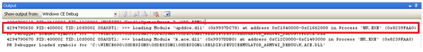
Check the log for
other messages including the text UPDD, particularly when touching the
screen. In the event of USB errors useful information is output in the log.
Typical touch related entries are as follows, showing the driver loading and
starting to function:
4294830336
PID:400002 TID:10f0002 DEVICE!RegReadActivationValues
RegQueryValueEx(Drivers\BuiltIn\updd\BusPrefix) returned 2
4294830337 PID:400002 TID:10f0002 OSAXST1: >>> Loading Module
'upddce.dll' (0x831B7BF8) at address 0xC1200000-0xC12EB000 in Process
'NK.EXE' (0x81D7FCA0)
4294830366 PID:400002 TID:10f0002 OSAXST1: >>> Loading Module
'k.ace.dll' (0x831B7D30) at address 0xC1010000-0xC1162000 in Process 'NK.EXE'
(0x81D7FCA0)
4294830401 PID:400002 TID:10f0002 OSAXST1: >>> Loading Module 'k.winsock.dll'
(0x831B7E68) at address 0xC0DF0000-0xC0DF5000 in Process 'NK.EXE'
(0x81D7FCA0)
4294830438 PID:1990002 TID:1160002 [NOTIFY] HandleSystemEvent 7 /ADD ETM1:
4294830659 PID:400002 TID:10f0002 Dll Process Attach
4294830659 PID:400002 TID:10f0002 DdsiTouchPanelAttach+
4294830659 PID:400002 TID:10f0002 DdsiTouchPanelAttach-
4294830659 PID:400002 TID:10f0002 Console NOT redirected for process 0x400002
4294830662 PID:400002 TID:10f0002 TBUPDD: 0 CDriver::CDriver()
4294830662 PID:400002 TID:10f0002
4294830663 PID:400002 TID:10f0002 TBUPDD: 0 CreatePrimaryDevice()
4294830663 PID:400002 TID:10f0002
4294830663 PID:400002 TID:10f0002 TBUPDD: 0 Created primary device
4294830663 PID:400002 TID:10f0002
4294830663 PID:400002 TID:10f0002 TBUPDD: 0 Created device map entry
4294830663 PID:400002 TID:10f0002
In this example
an exception has been thrown on the first touch (possibly due to the missing
Touch Stylus component):
4294869773
PID:400002 TID:5300062 TBUPDD: 1748 CUSBConnection::ReadInterruptDataThread
read 1 bytes
4294869783
PID:400002 TID:526000a TBUPDD: 1748 CCEMousePort::MouseEvent 41335 43949
4294869827
PID:400002 TID:526000a
4294869827
PID:400002 TID:526000a !ERROR: Calling EnterCriticalSection on a CS
(c0fe2fa0) that is not initialized!
4294869852
PID:400002 TID:526000a Coredll: DEBUGCHK failed in file
d:\yzkiqfe\private\winceos\coreos\core\dll\cscode.c at line 117
4294869881
PID:400002 TID:5300062
4) Enable UPDD
debug log information
Additional UPDD
debug information can also be seen by setting the tbupdd.ini debuglevel
setting to 5.
TBUPDD.INI file
[UPDD]
Debuglevel=0x00000005
The USB
component also shows more debug information when executed in a debug build.
5) File based
debug
Now available in build 4.1.10 (Nov 2012 build) and 5.0.2 you can enable a
file based debug log if the standard debugging facilities are unavailable,
especially when installing the driver post image creation.
To enable file
based debugging define these settings:
[updd]
DebugLevel=0x00000003
FileDebug=0x00000001
Under CE the
file produced is /application data/updd.log.
FileDebug=0x00000000
is OFF.
If after
following the steps above you are unable to resolve the issue please send the
log file to us for further analysis.
Serial debug connection
If you wish to use a Serial connection to the Windows
CE device for debug purposes we did document many years ago that there is a
consideration that is not always made clear in the Microsoft documentation. A null modem cable is required, but
this differs from a standard null modem cable in that the RI pin is connected
straight through. Without this connection it will be impossible to make a
serial connection from the NT host to the Win CE device. Nowadays most
system integrators do not debug over serial so we are not sure if this is
still a valid issue.
Port interface issues – important
Serial
Touch-screens may be connected to a CE device via a
standard serial (COM). A CE image builder should bear in mind that the
default CE image generated by platform builder might well make assumptions
regarding the usage of such ports. E.g. debug output will be sent to the
first physical COM port, preventing its use. By default, CE creates two com
port instances, Com 0 and Com 1. Com 0 is used as the debug port and relates
to the physical port com 1. Com 1 is therefore the first port that can be
used by the touch screen that actually relates to the physical Com 2 port.
Many customers have been unable to get their touch
screens working with a default CE build until they have plugged the touch
screen into com2 or changed the BIOS so that serial port is referenced as
Com2, although the references in the CE build refer to com 1 !!!!
In some circumstances the CE builder will need to
amend the CE configuration to alter the default serial port behavior. If you
are not familiar with this procedure we have technical bulletin that covers
this subject.
Port initialisation
We have discovered that with serial communications on
some motherboards if we set up UART flow control options then we receive
either no data or garbage. When this setup is omitted the serial port works
as expected. This is fine for serial controllers that do not need either a
specific state or change of state in the CTS/RTS lines in order to operate.
We have introduced a device level setting called
“IgnoreDCB” and if it is set to 0x00000001 then the com port flow control
initialisation is skipped.
[updd\Parameters\1\]:IgnoreDCB = 0x00000001
We found that the TI OMAP Platform motherboard
required this setting.
This is also used for the Zytronic ZXY100 controller
on ARM hardware where setting DCB causes rubbish to be read.
USB
The CE image must be amended to support the USB host
controller (this is the system’s USB host controller and NOT the USB touch
controller). Consult the manufacturer’s documentation and or Platform Builder
help for details of how to achieve this with the particular model of hardware
in use. A 3rd party driver might be required for the host controller,
although this has not the case for the hardware we have tested so far. To
ensure the CE system’s USB host controller is functioning use a HID mouse
prior to testing the USB touch controller.
PS/2
PS/2 support needs to be reinstated for the new
driver as and when required….
Known issues
The list of known issues is as follows:
1) Device warning message in debug log with touch
working fine
When viewing the system debug log you may find an entry in a system where the
touch is working fine that specifies:
DEVICE!InitDeviceContent: can not Init Device content for
'Drivers\USB\LoadClients\2801_1\Default\Default\Tbupddceusb,error code 2404’
!UPDD_USB: Could not ActivateDevice
Drivers\USB\LoadClients\2810_1\Default\Default\Tbupddceusb 0x00000964
This error is documented thus “System error code 2404 means "The device
is in use by an active process and cannot be disconnected." This error
code may also display as "ERROR_DEVICE_IN_USE" or as the value
0x964.
We aren't quite sure why the "already in use" error occurs, but our
suspicion is that it relates to the fact that the module load is attempted at
two points.
1) During the enumeration and matching phase (i.e. when the OS is looking for
a matching driver).
2) When the USB system activates the driver.
We think this message is simply a warning that the module is already loaded.
We believe this only occurs in Win CE7.
This error should not be ignored if the touch is not working!
2) After installing driver image worked once but failed
to boot on subsequent reboots
Customer determined that the image had increased in size and was too big for
the flash disc allocated space. They increased the value associated with
setting PLAT_IPSM_START_OFFSET and subsequent boots were OK.
3) Hot plug of device not working
Hot plugging is not fully supported, in some cases this is due to limitations
of the USBHC driver and / or USBHC hardware component.
As of 23/02/12 improved hot plug supported added.
With UPDD CE release 5.1.nnn we identified changes required to further
improve hot plug capabilities. This can be added whenever required.
4) Missing \application data\updd folder and therefore
no tbupdd.ini
This caused issues with the driver. The user had used #includes in
platform.reg, platform.bib and platform.dat. However it was not recognised in
platform.dat, so tbupdd.dat was not included. As a consequence tbupdd.ini
file was not included in the build.
5) Exception shown in system log when touching – touch
no longer working
This issue was initially experienced on one system running CE 5 but another
customer reported the same issue under CE6 when switching computer board and
BSP. Our investigation revealed that the system appeared to be loading 2
instances of the driver DLL and in one of the instances certain UPDD
internals were uninitialized such that the touch processing crashed. The driver
provides entry points to load both as a “builtin” driver and a GWES client.
Ordinarily both sets of entry points are called and the second call
references the same DLL instance, suggesting that the same system process is
responsible for both calls. For historic reasons the built-in load initiates
the main driver logic, with the GWES call initialising the mouse interface.
In this system we were seeing the DLL instance communicating with USB and
reacting to touch, but it was referencing GWES related items that had only
been initialised in the other instance and causing an exception.
To overcome this issue we have made a change to the driver such that all UPDD
internals are initialized by the GWES interface and therefore we believe that
there is no longer any requirement for the DLL to be invoked as a built in
driver, such that the following line can be removed from the .reg file:
[HKEY_LOCAL_MACHINE\Drivers\BuiltIn\updd]
"dll"="upddce.dll" << remove this line only
Until we are able to undertake extensive testing that it is OK to remove this
entry in all cases it remains as part of the distributed .reg file and should
be removed as required.
Note: This line should only be removed if using the upddce.dll dated July
2012 or later.
6) Serial not working
We have had incidences whereby users have configured both UPDD USB and Serial
devices in the UPDD configuration when using serial devices and reported that
serial is not working. If the driver finds the USB vid
(HKEY_LOCAL_MACHINE\Drivers\BuiltIn\updd) definition in the registry it
determines that it is dealing with a USB configuration and ignores any serial
configuration. Ensure USB settings are not defined when working with a
serial device.
7) Touch not working although debug logs showed GWES and
Cesendinput driver interfaces both working as expected
We raised our concern that there was a unspecified CE configuration that was
preventing the touch interface working. After further investigation the
customer reported that they had “tried to patch the Microsoft HID mouse
driver in the past to work with the HID Touch device and this driver had
accidently been included in the image.” Once this driver was removed the
touch started working.
8)
Multi-core
processor issue
Customer reported that before enabling SMP (Symmetric Multi Processor) the
touch function works well. After SMP enabled, touch function fails.
Here is the debug log showing the start up issue with SMP enabled:
PID:00400003 TID:01770062 Warning! Kernel DLL 'tbupddceusb.dll' is registered
for thread creation/deletion notification.
To improve performance if you dont need thread notifications call
DisableThreadLibraryCalls from inside
PID:00400003 TID:01770062 DEVICE!InitDeviceContent: can not Init Device
content for
'Drivers\USB\LoadClients\1240_3074\Default\Default\Tbupddceusb,error
code 2404'
In this instance restrict the driver to using one processor as described in the notes above.
9)
Calibration
issues:
Customer reported with CE 5 “When I start tbcalib.exe, I get the message:
‘tbcalib’ cannot be accessed.” This was from Windows Explorer and further
investigation revealed that the hidden attribute was enabled and this seemed
to prevent its execution.
TBcalib crashed when used in an image that did not contain a graphical shell.
Since Nov 2013 this dependency has been removed.
Some customers have reported that the built in calibration icons are not
shown, in this case embedding image calib_cr_32_n_p.bmp as
described in the calibration section has resolved the issue.
10) USB xhci driver
We had a customer report that the touch would not work under Win CE X86 and
after further investigation found that deactivating the xhci driver solved
the problem. We do not know why but we are just reporting this as an
observation.
Limitations
Known limitations to be addressed as required:
USB hot plug support – can be added as and when
required.
USB and serial and i2c (Nov 12) support only. Other
interfaces to be added as required.
No sound support.
Dynamic rotate untested.
Hardware based eeprom storage not supported.
Limited testing of software based eeprom calibration
storage.
No GUI settings dialog (UPDD Console) to allow for
dynamic setting changes.
Contact
For further
information or technical assistance please email the technical support team
at technical@touch-base.com.
|
