|
|
EEPROM calibration support |
|||||||||||||||||||||||||||||||||||||||||||||||||||||||||||||||||||||||||||||||||||||||||||||||||||||||||||||||||||||||||||||||||||||||||||||||||||||||||||||||||||||||||||||||||||||||||||||||||||||||||||||||||||||||||||||||||||||||||||||||||||||||||||||||||||
|
Revision 1.24 – 2nd Dec 2015 |
||||||||||||||||||||||||||||||||||||||||||||||||||||||||||||||||||||||||||||||||||||||||||||||||||||||||||||||||||||||||||||||||||||||||||||||||||||||||||||||||||||||||||||||||||||||||||||||||||||||||||||||||||||||||||||||||||||||||||||||||||||||||||||||||||||
|
www.touch-base.com\documentation\General |
||||||||||||||||||||||||||||||||||||||||||||||||||||||||||||||||||||||||||||||||||||||||||||||||||||||||||||||||||||||||||||||||||||||||||||||||||||||||||||||||||||||||||||||||||||||||||||||||||||||||||||||||||||||||||||||||||||||||||||||||||||||||||||||||||||
|
Some pointer device controllers have on-board EEPROM (Electrically Erasable Programmable Read Only Memory). EEPROM can be used to store information pertinent to the controller and also offers a memory storage area for applications and drivers to store data. One of the main uses for this memory with UPDD is to store the calibration data within the controller rather than locally on a system.
In all cases an absolute pointer device needs to be calibrated with the systems video display such that the point of contact is aligned with the video image. UPDD calibration is performed by drawing points on the video display at known locations that are then touched and the touch co-ordinates are noted for the given point of display. The driver can then use this data to scale and map the touch input to the video location. This information, known as the calibration data, needs to be stored for future reference, such that the device is calibrated at each system power up. This information can be stored locally on the system within a file or externally in the controller’s EEPROM.
Given that UPDD supports 100’s of different pointer devices, all with different characteristics, our driver generally stores its calibration data locally within the system.
However, there are cases where it is desirable to store calibration data externally. This is especially true of systems where the calibration data cannot be stored locally, such as some embedded system configurations where the entire system is locked down and any changes made are lost when the device is powered off, typically embedded or Windows CE systems. In other cases it is desirable to calibrate a touch screen prior to usage on a similar system so that it is calibrated when first used and will only require recalibrating if the EEPROM calibration is inaccurate.
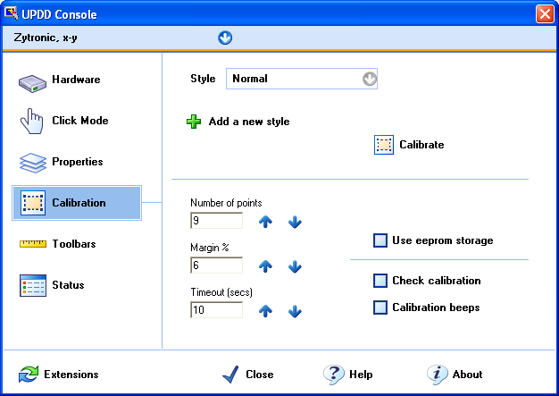
As and when we have been requested to support EEPROM
calibration for a given controller it has been added. When one of these
controllers is defined in the UPDD build and added in the UPDD Console as an
active device an EEPROM check box is shown on the UPDD Console, Calibration
screen.
When this EEPROM check box is enabled (or set internally in the UPDD settings), it indicates that EEPROM calibration procedure is utilised at the NEXT calibration. It is important to note that this setting enables the EEPROM calibration procedure such that at the point of calibration the EEPROM calibration procedure is invoked.
This checkbox setting changes the UPDD device setting ‘eeprom calibration’. EEPROM implementationsEEPROM calibration falls into two distinct categories;
·
Firmware calibration whereby the controller’s built-in
calibration procedure is invoked such that, following calibration,
co-ordinate data is scaled to the video resolution · UPDD native calibration storage whereby the UPDD calibration data is stored in the controller’s EEPROM for later retrieval. UPDD EEPROM frameworkFirmware calibration procedures are built into the UPDD Calibration program and invoked as required.
UPDD native calibration is implemented in the UPDD EEPROM framework and consists of the following components: · The UPDD API has a read and write EEPROM API to read and write raw data to the controller’s EEPROM. These API’s implement the specific code needed to interface with a controller’s firmware to store and retrieve data in the controller’s EEPROM. · The UPDD calibration program utilises the API calls to read and write the calibration data. · The UPDD daemon process (aidaemon) is responsible for retrieving the stored calibration data at appropriate times; system start up, add device etc. Points of retrieval are dictated by a number of UPDD settings as described below. · The UPDD Console also retrieves the calibration data at the time the EEPROM check box is enabled. · Under Windows CE the driver retrieves EEPROM data directly
EEPROM calibration is implemented in UPDD by the use of specific EEPROM protocol code that is written for each controller. When a controller is defined in our controller production system we indicate the EEPROM protocol id to use to enable EEPROM calibration.
The protocol id also indicates what EEPROM method to use, as described below
Enabling EEprom protocolsGive that the EEPROM interface to each controller is unique there is separate protocol code written for each controller. When we define a controller we identify the protocol to use. If the EEPROM protocol setting is blank then the EEPROM option in the UPDD Console will not be shown
The protocol setting protocol identifiers are shown below with an indication when EEPROM support was last tested. For sheer convenience most EEPROM testing is carried out in Windows and in theory if it works in Windows it should work in other OSes. We will investigate further is this proves not to be the case.
The EEProm protocol id settings are held in the UPDD settings file, TBUPDD.INI, within the branch [updd\paramaters\n] (for configured/active controllers) and [updd\parameters\controller\ts00n] the default settings for controllers supported by the driver:
eeprom calibration=0x1 eeprom protocol=’protocol id’
For CE see EEprom notes in the CE documentation. At the time of writing the CE driver only supports EEprom in controllers whereby UPDD calibration is being stored and not firmware based calibration controllers. This support will be added as required.
If you are using a driver which supports one of the above controllers but does not show the EEprom option then it is likely the EEprom setting was/is not defined in the definition of the driver at build time. If this is the case contact Touch-Base to request an updated build. Read processThe following dialog is shown during the read process unless the setting eepromreadsilent is set to 1. This can be set using the UPDD command line utility i.e. tbutils nodevice setting dw eepromreadsilent 1
If valid calibration data is held in the controller it is utilized otherwise calibration data held locally is used.
The read mechanism has a degree of auto retry and recovery code but repeat read failures or invalid CRC will result in the following dialogue being displayed:
This could happen whereby EEPROM setting is enabled but a new controller, without any valid calibration data is connected.
The tbupdd.ini file setting eepromreadstatus is the return code from the last execution of the eeprom read function of tbcalib, with 0 meaning success. NotesWrite EEPROM at initial startupStarting with 5.1.1463 we have introduced a new setting eepromwriteatfirststartup to request that default calibration data held in the driver’s setting file be written to EEPROM when the aidaemon process starts. If this is set in the release package then EEPROM write is attempted following install when aidaemon starts (immediately and at each reboot).The setting is set to 0 when the update has been successful. Storage requirementsThe UPDD EEPROM framework requires the following amount of storage.
number of points x 4 + 22 bytes
So
4 points needs 38 bytes 9 points needs 54 bytes 25 points needs 122 bytes
16 bytes is to hold the calibration style, which must be a maximum of 15 bytes (15 + endofstring)
Starting with version 5.1.656 we now also store the video resolution of the associated monitor. This requires a further 4 bytes. Reading and writing eeprom calibration dataThe reading and writing of native UPDD EEPROM data is built into the UPDD calibration program tbcalib. This program export a number of EEPROM command line options; eeprom – read EEPROM calibration data and eepromwrite - write calibration data from the UPDD settings file to EEPROM. Viewing EEPROM configuration and dataThere are a number of commands available to show the eeprom calibration data.
One such command is “tbutils listcalibration”, as seen below. This shows eeprom information for a controller with eeprom support, lists the protocol id (in this example zytronic-usb), indicates if eeprom is enabled and shows the eeprom content.
Adding EEPROM supportWe can add support in UPDD for any EEPROM enabled controller as required once supplied the technical documentation which describes the controller’s EEPROM calibration interface. ProtocolFor UPDD to be able to store its calibration data in EEPROM the driver needs firmware commands to read and write variable length data to a reserved location.
If using USB we prefer to be able to process the data via USB Control Requests via Endpoint 0. When reading the data this can either be received via the normal interrupt pipe or, preferably, in the data part of the USB Control Request. When passing via the data part of the control request the data may need to be processed in 64 byte blocks. EEprom support methodsIf you are a controller manufacturer and would like to add EEPROM capabilities to you controller, we are aware of three methods that have been utilised as described below: Raw ModeFirmware commands are used to specify that raw blocks of data can be stored and retrieved from EEPROM. In this mode, UPDD simply stores and retrieves the calibration from the controllers EEPROM.
This is the simplest method to implement for both the firmware developers and our driver as the EEPROM read and write functions are already built into the UPDD calibration program. Formatted modeThe controller’s firmware dictates the format of the calibration data passed to the controller which is further processed by the controller. The co-ordinate data is then scaled and mapped to a grid co-ordinate range, based on the formatted data. In this case the calibration program has to gather calibration data as dictated by the data format requirement. Co-operative modeThe controller’s firmware exposes calibration commands such that the calibration program issues a firmware command for each calibration point displayed and the firmware captures the calibration points in real-time. The number of calibration points and the pattern used is dictated by the firmware’s requirements. The co-ordinate data is then scaled and mapped to a grid co-ordinate range, based on the capture calibration information. Testing EEPROM supportOnce a controller is supported within the UPDD EEPROM framework there are a number of commands that can be used to test support as described here. ContactFor further information or technical assistance please email the technical support team at technical@touch-base.com
|
||||||||||||||||||||||||||||||||||||||||||||||||||||||||||||||||||||||||||||||||||||||||||||||||||||||||||||||||||||||||||||||||||||||||||||||||||||||||||||||||||||||||||||||||||||||||||||||||||||||||||||||||||||||||||||||||||||||||||||||||||||||||||||||||||||