|
If the touch device is known to be capable of multi-touch output it is best to capture this data in Windows 7 / 8 so that the device enters multi-touch mode.
Using this tool we are trying to capture the following data associated with the controller:
For an overview of some of the USB terminologies used in this document and seen in the USBlyzer dialogs see our USB basics document.
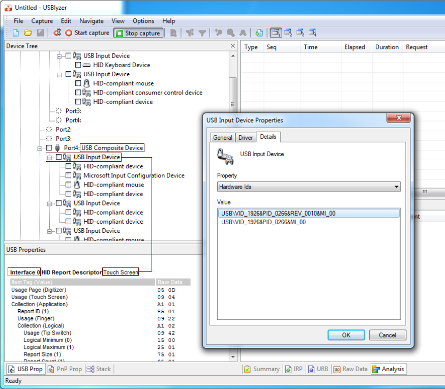
Download and install USBlyzer. Invoke the program and identify the touchscreen from the list of USB devices. In this example the touch device is registered as a USB Composite Device comprising 3 x USB Input Devices all of which would list the vendor and product id of the touch device: USB Vendor and Product id
As stated the above touch device is registering as a composite device, meaning that it has a number of interfaces and the tree is showing 3 x USB Input Devices. The first entry is showing as the touch entry on Interface 0. This is the device we need to support. The other entries are likely to be Tablet, Mouse and even Keyboard entries. Depending on the OS in use the device will output Touch, Tablet or Mouse packets. With UPDD we try and configure devices to always output touch data packets irrespective of the OS in use so we are only interested in the touch mode initialisation and touch data format.
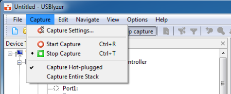
Important note: Some touch devices, such as non HID compatible or devices running in an HID mode other than ‘touch’ mode may not be listed as a ‘Touch’ device. In this case try to identify the touch device as best as possible which, for example, may be listed as a digitizer, mouse or other type of device. This is made easier if you know the vendor id of the device. HID enumerationNext select to capture device information when the device is enumerated on the system to see if HID places the device in any special mode of operation:
Now identify the touch device in the Device Tree and click the check box next to all the entries related to the touch device to indicate this is the device to be captured.
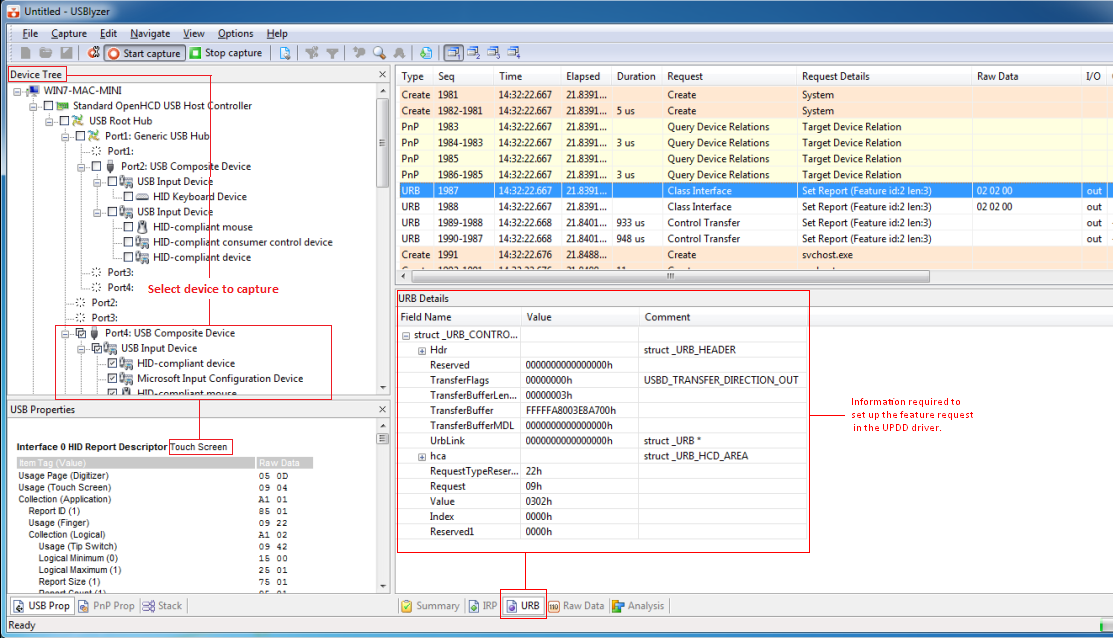
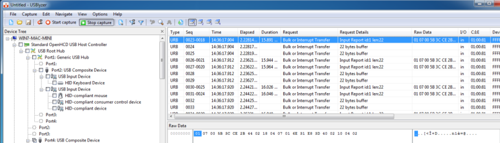
Next, start recording the traffic and disconnect, reconnect the device (or enabled / disable the device in the Device Manager if it cannot physically be unplugged). In this instance the device has indicated in the USB descriptor that it is capable of more than 1 touch and we can see below the USB feature request sent by Windows 7 HID to inform the controller that the driver (in this case the native HID driver) supports dual/multi-touch and that it should run in dual/multi-touch mode. This captured data allows us to set up the correct USB request in UPDD requesting the device runs in multi-touch mode, irrespective of the OS in use. Some controllers only output single touch data (commonly known as Mouse data) in non Win 7 OS or in some case none at all.
Touch data packet captureTouching the touch screen will now record the touch data exchange, here with a single touch:
And dual touch data:
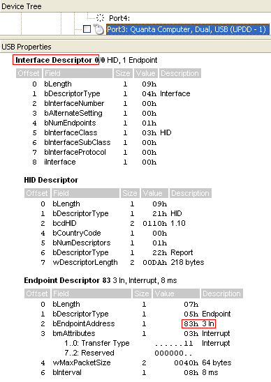
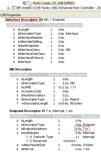
The recordings can be saved at appropriate times and the log files sent to us for analysis. USB interface and endpoint usageUPDD has been used for many years to support touch screens and in the majority of this time we have mainly dealt with single touch HID and non HID USB devices. In the majority of these devices the touch data has been delivered on Interface 0 and the first ‘non control point’ endpoint (USB controllers use endpoint 0 as the control endpoint). To cater for this configuration our Windows driver has always expected touch data to be delivered on this interface. However, with the advent of dual and multi-touch devices this interface can no longer be assumed to be the standard interface. With UPDD 5.0.2 and above the controller is configured such that it holds the interface and endpoint as specific configuration data. Here are 3 examples of different UPDD supported controllers showing their interface and endpoint usage.
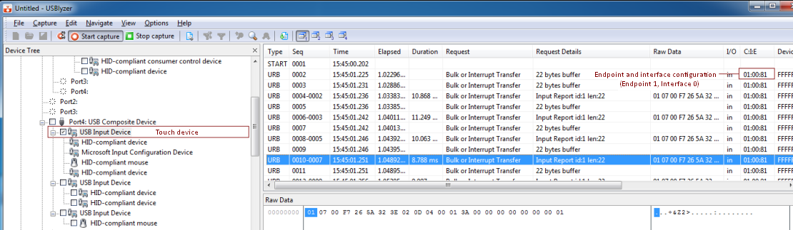
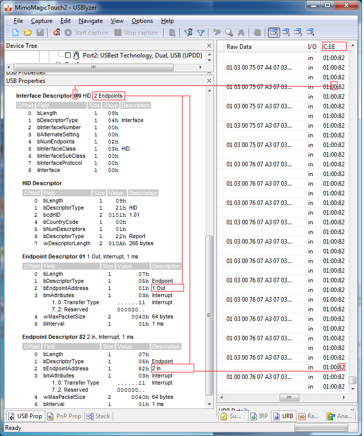
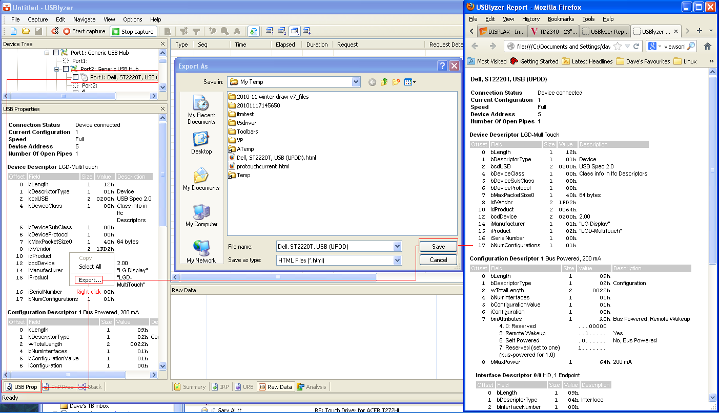
It is important when using USBlyzer to capture both the touch data but to also note the interface and ‘in’ endpoint used to deliver the data and to view the number of endpoints associated with the interface. The entire USB properties for a given device can be exported to a HTML file as shown here. Please send this file along with the log files.
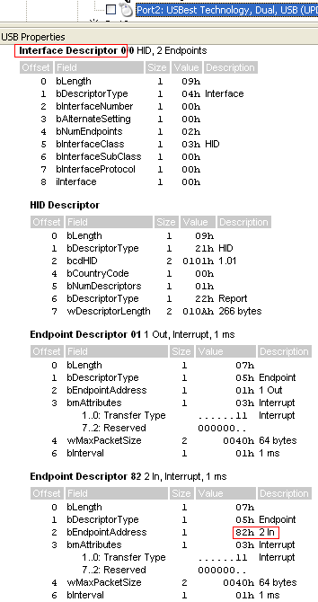
In this example the touch data is seen on interface 0, ‘In’ endpoint 2 (82) and there are 2 endpoints associated with the Interface.
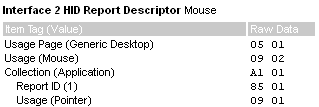
Maximum Data Packet SizeThe USB properties, for a given Endpoint, will show the wMaxPacketSize. In the example above it can be seen that this is defined as 40hex / 64 decimal. In all cases we would expect this value to be the same or greater than the touch data packet and therefore one read request on the USB device would receive all the touch packet data. We have come across one device whereby the touch packet data was greater than the wMaxPacketSize which was surprising and we think an error in the device USB descriptor. At a driver level it does mean we have to initiate additional reads to receive one complete touch data pack. When submitting any USBlyzer logs it is worth indicating the wMaxPacketSize shown for the device. This image shows the details of the touch device that required more than one read to receive a complete touch data packet. Mouse entry exampleIf a touch device is listed as a ‘mouse’ device you will see an entry similar to the following HID descriptor and the captured data when touching the screen. In this example the ‘mouse’ data is on HID interface 2:
|